


724-746-5500 | blackbox.com
Page 46
724-746-5500 | blackbox.com
Chapter 4: E2 Controller
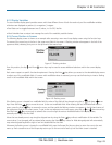
4.1.2.2 Contrast Adjustment
Press and hold the Alarm and Prg keys, then use the Up and Down keys to adjust the contrast.
4.1.2.3 Alarms
Alarm conditions activate a red LED indicator that backlights the alarm function key. As an option, an alarm condition may also be
enunciated by an audible alarm signal. An alarm is acknowledged by pressing the alarm key. This calls up alarm display screen(s)
that provide a text message detailing the alarm condition(s). After an alarm condition is corrected, the alarm can be cleared by
pressing the alarm key.
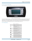
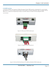
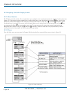
4.1.3 Controller I/O Module
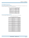
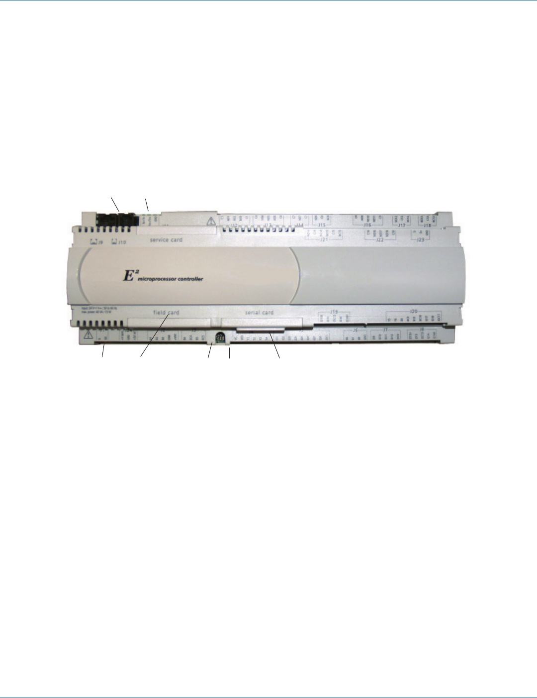
The controller is a microprocessor-based I/O module mounted inside the A/C system electric box (see Figure 4-2). The controller
I/O module contains the software that manages the operating parameters of the A/C system.
1 2
7 6 5 4 3
Figure 4-2. Controller I/O module.
Controller I/O Module Layout
The controller I/O module contains the logic and input/output terminals. See Figure 4-2 for details of the controller I/O module
layout. The item numbers that follow coincide with the call-outs in Figure 4-2.
1. Connection (J10) for interface display panel
2. Connection for pLAN (J11)
3. Hatch for BMS or network card
4. Power on LED (Yellow)
5. Signal LEDs (Red, Yellow, Green)
6. Hatch for expansion I/O module(s)
7. Power connector (J1)