


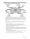
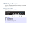
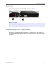
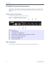
ET0100A Physical Description
ETEP Installation Guide 15
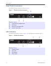
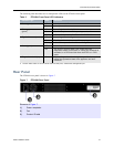
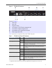
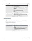
The following table describes how to interpret the LEDs on the ET0100A front panel.
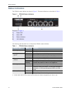
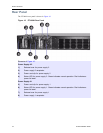
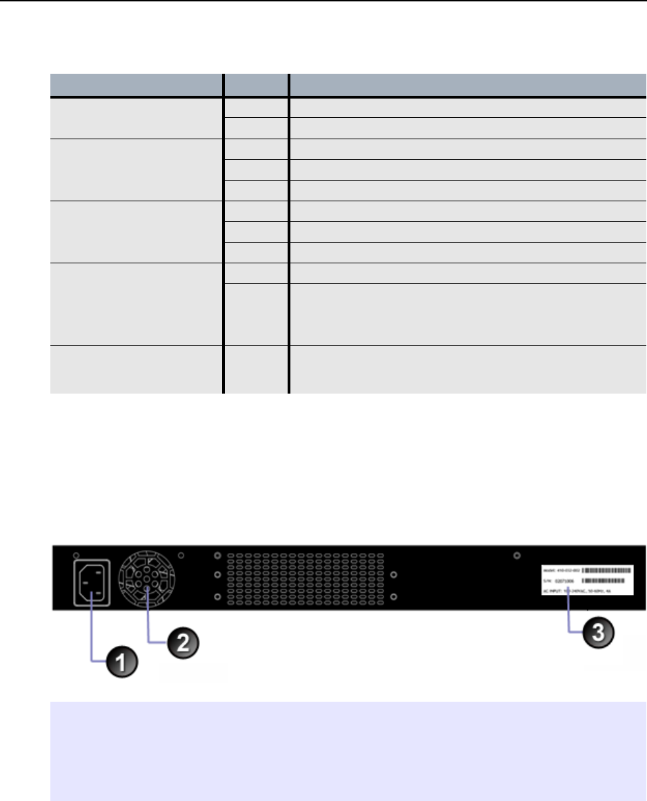
Rear Panel
The ET0100A rear panel is shown in Figure 7.
Figure 7 ET0100A Rear Panel
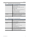
Table 2 ET0100A Front Panel LED Indicators
Indicator Light State Indication
Power (green) Off Unit is powered off.
On Unit is powered on.
Ethernet port status
(green)
a
a. The link status LEDs are on the remote and local data ports, and Ethernet management port.
Off Loss of signal on the 10/100 link.
On The link is up but no traffic is passing over the link.
Blinking Indicates the presence of traffic on the 10/100 link.
Gigabit link status (amber)
a
Off Loss of signal on the Gigabit link.
On The Gigabit link is up but no traffic is passing over the link.
Blinking Indicates the presence of traffic on the Gigabit link.
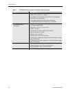
Alarm (green) Off Normal operation.
On The unit is in an error state. This occurs when the
diagnostics detect a boot failure, a critical error threshold is
exceeded, or a FIPS test fails when the ETEP is in FIPS
mode.
Diagnostic code display On Displays diagnostic codes during boot up. After boot up, it
reflects the operational state of the appliance and error
conditions.
Elements of Figure 7:
1) Power receptacle
2) Fan
3) Product ID label