


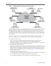
Product Overview
18 ETEP Installation Guide
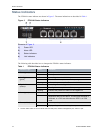
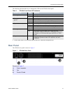
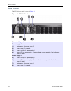
Rear Panel
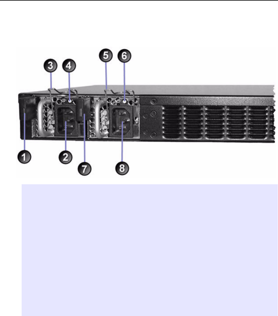
The ET1000A rear panel is shown in Figure 10.
Figure 10 ET1000A Rear Panel
Elements of Figure 10:
Power Supply # 2
1) Release lever for power supply 2
2) Power supply 2 receptacle
3) Power cord clip for power supply 2
4) Status LED for power supply 2. Green indicates normal operation. Red indicates a
power fail state.
Power Supply # 1
5) Power cord clip for power supply 1
6) Status LED for power supply 1. Green indicates normal operation. Red indicates a
power fail state.
7) Release lever for power supply 1
8) Power supply 1 receptacle