


Application Note
BlueBox Demo-Board for the digital sensors
SMB365 (acceleration) and SMD500 (pressure)
Bosch Sensortec
AN18002
Rev. 1.0
Page 34
© Bosch Sensortec GmbH reserves all ri
g
hts even in the event of industrial propert
y
ri
g
hts. We reserve all ri
g
hts of disposal such
cop
y
in
g
and passin
g
onto third parties.
7211RB11.
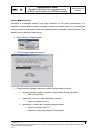
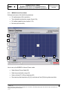
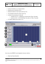
23. Hysteresis and Threshold level settings
• for global interrupt conditions
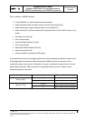
o Threshold and Hysteresis for all axes are given in digits (d) of a 7bit word
o 1d corresponds to 4 LSB (16mg in low g mode and 0.08g in high g mode)
• for axis individual interrupt conditions
o Threshold for each axis is given in digits (d) of a 5bit word
o 1d corresponds to 16 LSB (64mg in low g mode and 0.32g in high g mode)
o Hysteresis for each axis is given in digits (d) of a 3 bit word
o 1d corresponds to 64 LSB (256mg in low g mode and 1.28g in high g mode)
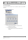
24. Selftest selection
• Off/On (disable/enable) selftest to check signal evaluation path (MEMS plus ASIC)
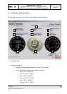
25. Interrupt signal output LED
• LED off = interrupt inactive; LED on = interrupt active
• No software-function but direct readout of the SMB365 internal interrupt logic pin
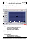
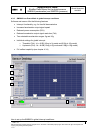
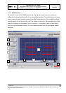
26. Acceleration signal output screen
• Acceleration sensitive digital signal, given in LSB, g or m/sec²
• 1LSB corresponds to 4mg in low g mode and 20mg in high g mode
27. Ordinate unit selection (acceleration)
• choose proper unit of acceleration sensor output signal (g, m/s² or LSB)
28. Output signal reference color
• X-axis = green Y-axis = yellow Z-Axis = red
29. Ordinate scale selection (acceleration)
• full scale: ±512LSB, ±20m/s² or ±2g in 2 g range (resolution: 1LSB = 4mg)
• full scale: ±512LSB, ±100m/s² or ±10g in 10g range (resolution: 1LSB = 20mg)
30. Abscissa scale selection (timebase)
• select from 2000 to 50 msec/div