


Matrix Switching System—Instruction Manual Page 27
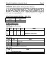
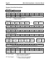
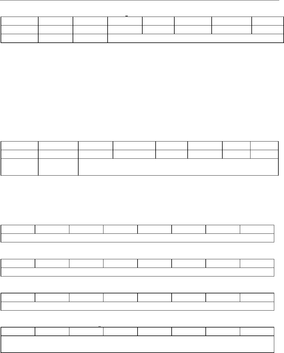
Address Byte (Command Type A and B)
7 6 5 4 3 2 1 0
BT X CRC M4 M3 M3 M1 M0
Broadcast Reserved CRC Machine ID (5-bit address)
BT: Broadcast 0: Instruction for one machine with matching Machine ID
1: Instruction for all machines
If BT = 1, machine will not return a response packet.
If BT = 0, machine must respond
CRC: CRC-8 0: Host (computer) does not append a CRC byte at end of command
packet
1: Host appends a CRC byte to end of command packet
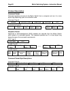
Instruction Code Byte (Command Type A and B)
7 6 5 4 3 2 1 0
VAR X I5 I4 I3 I2 I1 I0
Variable
Length
Reserved Instruction Code (6-bit command)
VAR: Variable Length 0: The command packet is 4 bytes with Output and Input bytes
1: The command packet is variable length and contains a
length byte indicating the number of Output and Input bytes
Length Byte (Command Type B only)
L7 L6 L5 L4 L3 L2 L1 L0
Number of Output and Input Bytes to follow not including CRC
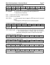
Output Byte (Command Type A and B)
O7 O6 O5 O4 O3 O2 O1 O0
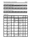
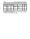
Refer to Command Table
Input Byte (Command Type A and B)
I7 I6 I5 I4 I3 I2 I1 I0
Refer to Command Table
CRC (Command Type A and B)
C7 C6 C5 C4 C3 C2 C1 C0
CRC-8 calculated from all bytes in packet.
Appended if CRC bit set in Instruction code