Page 4 Matrix Switching System—Instruction Manual
Input/Output Jacks
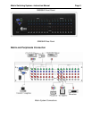
Dependent on the matrix model installed, the video signal input/output jacks are arranged in
either 4 or 8 columns of RCA female connectors. The connector rows from top to bottom are:
Y video (green), Pb/Cb video (blue), Pr/Cr video (red), right audio signal (red), and left audio
signal (white). The input and output jack channels are numbered from left to right as 1 to 8
(or 1 to 4). Refer to the drawing above for other types of connectors. The model numbers of the
matrix systems describe the number of input/output connectors. Example: Model SW404HD
has 4 input sets and 4 output sets.
Connecting Audio/Video Cable
The matrix supports various AV video signal sources. Users can connect inputs and outputs to
different audio/visual equipment such as: CD/DVD players, graphics workstations and number
displays, projectors, video recorders, displays, multiplexers, and etc.
Audio/Video Ports
The RCA Jack used is a standardized audio/video connector. It uses coaxial signal connections
in the center conductor and the outer ring for grounding. It will transmit digital audio signals and
video signals.
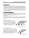
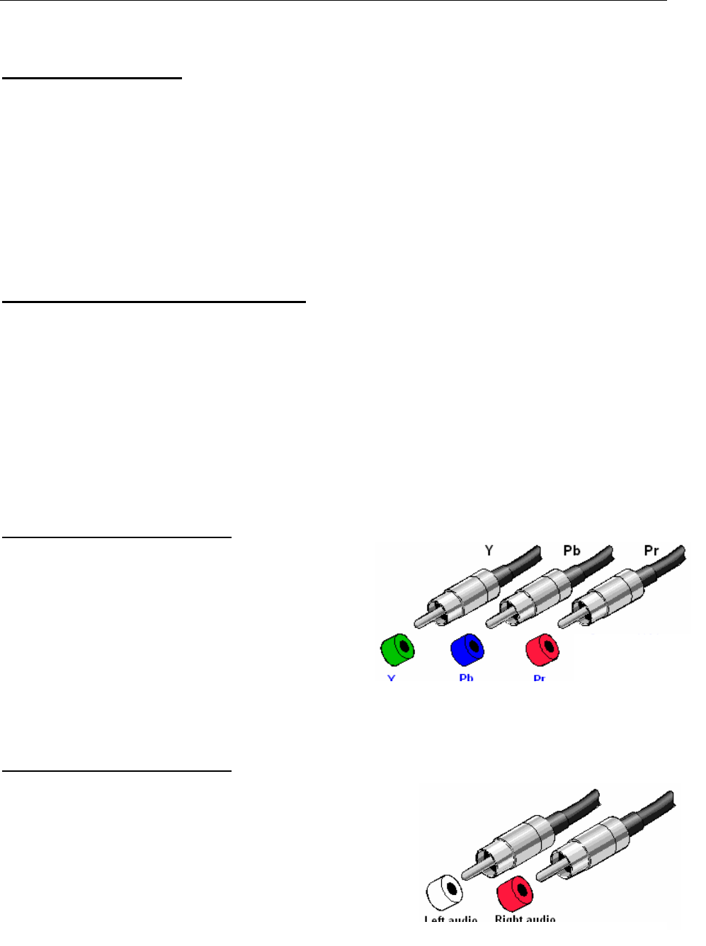
Video I/O (3-RCA) Connectors
The Y/Pb/Pr connector is a high definition digital TV
connector (color contour Y/Pb/Pr) capable of
connecting with high definition digital set-top box,
satellite receiver and various high definition
monitors and TV equipment. There are separate
connectors for the Y, Pb, and Pr signals.
YPbPr-RCA Connecting Cables
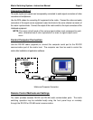
Audio I/O (2-RCA) Connectors
Connection of the RCA audio cables is as shown below:
Normally RCA audio connectors are in pairs separately
indicated by red for the right audio channel (R for right)
and black or white for the left audio channel (L for left).
The RCA stereo cable is in one set for both left and right
audio channels with each channel in one cable.
Audio Connecting Cables
Component
Video


