


Introduction Supported Devices
Spectrum Enterprise Manager Page10 SmartSwitch 6000
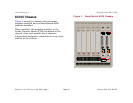
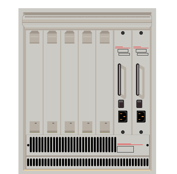
6C105 Chassis
Figure 1 shows the chassis with two power
supplies installed and no SmartSwitch 6000
modules installed.
When installed, the modules interface to the
Frame Transfer Matrix (FTM) backplane in the
chassis, thus each module has a separate,
independent backplane connection to every other
module in the chassis.
Figure 1: SmartSwitch 6000 Chassis
CaBLeTROn
SYST
e
MS
6C105
Smart
SWITCH
6000
Smart
SWITCH
6000
Smart
SWITCH
6000
Smart
SWITCH
6000
Smart
SWITCH
6000
100 • 125 VAC
200 • 250 VAC
50 •60 Hz
CaBLeTROn
SYST
e
MS
PDK 0 0 REDUNDANCY
6C205-1
B0096520019
SN
100 • 125 VAC
200 • 250 VAC
50 • 60 Hz
CaBLeTROn
SYST
e
MS
PDK 0 0 REDUNDANCY
6C205-1
B0096520019
SN