


xiii
Figures
Figure Page
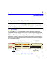
1-1 2E253-49R SmartSwitch 2200 Device............................................................................1-1
3-1 Tabletop or Shelf Installation...........................................................................................3-4
3-2 Attaching the Strain-Relief Bracket .................................................................................3-5
3-3 Attaching the Rackmount Brackets .................................................................................3-6
3-4 Installing the Device in a Rack ........................................................................................3-7
3-5 2E253-49R Rear View.....................................................................................................3-8
3-6 Straight Cable Connection ..............................................................................................3-9
3-7 Connection Using the RJ21 Angle Adapter.....................................................................3-9
4-1 LANVIEW LEDs ..............................................................................................................4-1
4-2 RESET Button.................................................................................................................4-7
B-1 Removing the Chassis Cover..........................................................................................B-4
B-2 Mode Switch Location .....................................................................................................B-5
B-3 DRAM SIMM connector Location....................................................................................B-7
B-4 Installing the DRAM.........................................................................................................B-8
B-5 HSIM and VHSIM Connector Locations..........................................................................B-9