


xiii
Figures
Figure Page
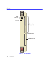
1-1 The SmartSwitch.............................................................................................................1-2
3-1 Installing an Interface Module .........................................................................................3-3
3-2 Connecting a Fiber Optic Segment to the SmartSwitch.................................................. 3-5
4-1 LANVIEW LEDs ..............................................................................................................4-2
4-2 RESET Button...............................................................................................................4-10
B-1 Module Mode Switch Location/Component Layout.........................................................B-2
B-2 SIMM Slot Locations .......................................................................................................B-4
B-3 Installing the DRAM.........................................................................................................B-5
B-4 HSIM and VHSIM Connector Locations..........................................................................B-6