


Installing Options
3-2 Installation
3.2 INSTALLING OPTIONS
If installing an optional HSIM or VHSIM, it must be installed in the SmartSwitch before
proceeding to Section 3.3. Complete instructions for installing an optional HSIM or VHSIM are
available in the applicable HSIM or VHSIM User’s Guide. For details on how to get manuals, refer
to the Related Manuals in the About This Guide preface. Refer to Appendix B for the HSIM or
VHSIM connector locations.
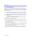
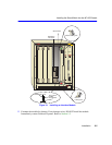
3.3 INSTALLING THE SMARTSWITCH INTO THE 6C105 CHASSIS
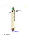
The SmartSwitch modules can be installed in any of the 5 slots that are available. To install a
module, refer to Figure 3-1 and proceed as follows:
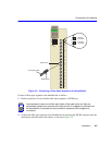
1. Remove the blank panel covering the slot in which the module will be installed. All other slots
must remain covered to ensure proper airflow and cooling. (Save the blank plate in the event
you need to remove the module.)
2. Carefully remove the module from the shipping box. (Save the box and packing materials in the
event the module must be reshipped.)
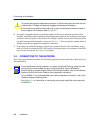
3. Locate the antistatic wrist strap shipped with the 6C105 chassis. Attach the antistatic wrist strap
to your wrist and plug the cable from the antistatic wrist strap into the ESD grounding
receptacle at the upper right corner of the 6C105.
4. Remove the module from the plastic bag. (Save the bag in the event the module must be
reshipped.) Observe all precautions to prevent damage from Electrostatic Discharge (ESD).
!
CAUTION
Failure to observe static safety precautions could cause damage to the SmartSwitch.
Follow static safety handling rules and wear the antistatic wrist strap provided with the
6C105 chassis.
Do not cut the non-conductive bag to remove the module. Damage could result from
sharp objects contacting the board or components.