


Connecting to the Network
3-4 Installation
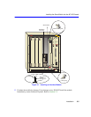
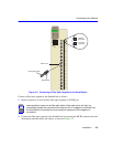
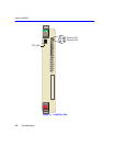
6. Locate the slot guides that line up with the number of the slot in which the module will be
installed. Install the module in the chassis by aligning the module circuit card between the upper
and lower metal rail guides of the desired slot, sliding it into the chassis, and locking down the
top and bottom plastic locking tabs, as shown in Figure 3-1. Take care that the module slides in
straight and properly engages the backplane connectors.
7. If the chassis in which the module is installed was powered down for the installation, turn it
back on. Check to see that the CPU LED settles at solid green after a few minutes. If the LED
does not turn solid green, see Chapter 4 for details.
3.4 CONNECTING TO THE NETWORK
This section provides the procedures for connecting segments from the network or other devices to
the SmartSwitch.
!
CAUTION
To prevent damaging the backplane connectors in the following step, take care that the
module slides in straight and properly engages the backplane connectors.
Ensure that the top plastic locking tab lines up with the desired slot number located on
the front panel of the chassis. Refer to Figure 3-1.
NOTE
If the SmartSwitch is being installed in a network using SmartTrunking, there are rules
concerning the network cable and port configurations that must be followed for
SmartTrunking to operate properly. Before connecting the cables, refer to the Cabletron
Systems
SmartTrunk User’s Guide
for the configuration information.
For the 6H258-17 and multimode fiber optic cable configuration information, refer to the
Cabletron Systems
Cabling Guide
.
See Section 2.1 for information on connecting using single mode fiber optic cable with
the 6H259-17.