


Chapter 5: Troubleshooting Procedures
5-4 CSMIM-T1 Hardware Installation Guide
During power-up and booting, it is more difficult to diagnose problems
because they can originate in the CSMIM-T1, the network, or the load
server host. However, the LEDs provide both a progress report and an
error display to assist you in troubleshooting.
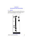
5.2 POWER-UP AND BOOT PROCEDURES
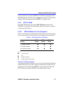
The CSMIM-T1 has two modes of operation: normal and set up. Normal
mode is the standard operational mode. SET UP mode provides access to
the ROM Monitor commands. Pressing the SET UP button on the front
panel puts the CSMIM-T1 into SET UP mode. When the CSMIM-T1 is in
SET UP mode, the SET UP LED lights.
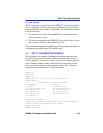
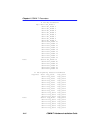
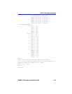
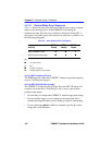
During the CSMIM-T1 power-up and boot sequence, the CSMIM-T1
runs a set of diagnostics. The system LEDs display the diagnostics’ status.
The CSMIM-T1 stops when it detects one of two error conditions (see
Table 5-2). The pattern of the system LEDs identifies the error condition.
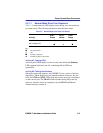
5.2.1 Normal Mode CSMIM-T1 Diagnostics
Following power-up or reset, the CSMIM-T1 enters normal mode. The
following subsections describe both the possible error and error-free
conditions that can occur during power-up and booting in normal mode.
NOTE
If an error occurs, save the status of these LEDs. Technical
support personnel can use this information to diagnose
problems.