


Unpacking and Installing Your ELS10-26
2-11
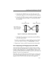
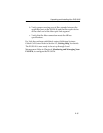
a. Check that the 10BASE-T device at the other end of the
twisted pair segment is ON and connected to the segment.
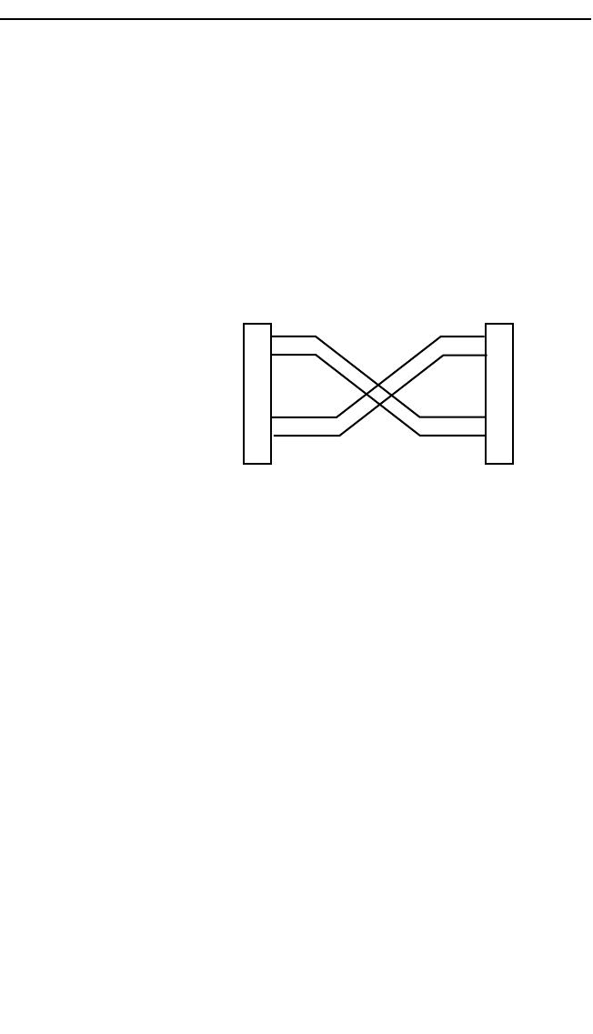
b. Verify that the RJ45 connectors on the twisted pair segment
have the proper pinouts (Figure 2-7) and check the cable
for continuity.
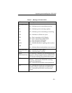
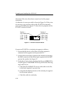
Figure 2-6. Cable Pinouts - (RJ45) Crossover Cable
c. Check that the twisted pair connection meets the dB loss
and cable specifications.
If a link is not established, contact Cabletron Systems Global
Call Center. Refer to Section 1.2, Getting Help, for details.
4. Repeat step 2, above, until all connections have been made.
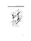
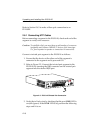
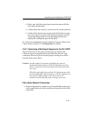
2.6.2 Connecting a UTP Segment to the FE-100TX
An FE-100-TX installed in port slot 27 is often used to provide a
connection between the ELS10-26 and a bridge, router, or switch.
Usually, in this configuration, a “straight-through” cable is used
and the Fast Ethernet Interface Module crossover switch shown in
Figure 2-7 is set to “not crossed over.”
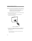
Normally, when connecting devices to like devices, crossing over
of the transmit and receive pairs must occur. Before connecting a
segment to the FE-100TX, check each end of the segment to
1
2
3
6
1
2
3
6
TX+
TX-
RX+
RX-
TX+
TX-
RX+
RX-
TO
ELS10-26 RJ-45 Port
TO
10Base-T Device Port
Note: RX+/RX- and
TX+/TX- must share a
common color pair.