


SEHI100TX User’s Guide 5-1
CHAPTER 5
CONNECTING TO THE NETWORK
This chapter outlines the procedure for connecting the SEHI to a network.
Ensure that the network meets the guidelines and requirements outlined in
Chapter 3, Installation Requirements and Specifications, before
installing the SEHI.
5.1 CONNECTING THE SEHI TO THE NETWORK
The procedure for connecting network segments to the SEHI varies
depending on the media and ports being connected. Refer to the following
list and perform the procedure described in the subsections that apply to
connecting the SEHI to a network:
• Network Ports Section 5.1.1
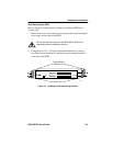
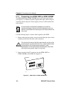
• EPIM-100TX Section 5.1.2
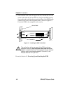
• EPIM-100FX or EPIM-100FMB Section 5.1.3
Prior to connecting the network cabling, check the connectors for the
proper pinouts as shown in Chapter 3.
5.1.1 Connecting to Network Ports
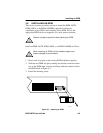
Attach UTP segments to the RJ45 network ports on the front panel of the
SEHI. Each RJ45 network port on the SEHI incorporates a polarity
detection and correction feature. The polarity detection and correction
feature allows the SEHI to pass data regardless of the polarity of the
twisted pair segment’s receive link. Operating in this condition is not
recommended; the segment should be removed from the network and
wired correctly by a technician.
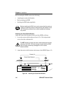
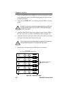
Connect the twisted pair segments to the SEHI as follows:
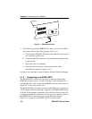
1. Plug the RJ45 connector from each twisted pair segment into the
desired network port on the SEHI. See Figure 5-1.
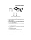
2. Plug the RJ45 connector at the other end of the twisted pair segment
into the other device as appropriate.