


The WAN Interface Configuration Screen
WPIM-T1/DDS User’s Guide 3-7
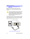
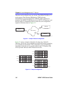
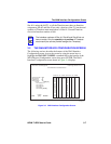
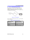
Site #1 is using the full T1, so all the Timeslots must have an Interface
assignment. Site #2 and Site #3 use only a fraction of the T1, but the total
quantity of Timeslots must match those of Site #1. Unused Timeslots
receive an Interface number of 000.
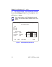
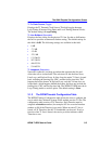
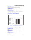
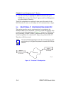
3.2 THE WAN INTERFACE CONFIGURATION SCREEN
The following sections describe the features of the WAN Interface
Configuration screen. Access the screen by using the arrow keys to
highlight the WAN INT CONFIG command field at the bottom of the
WAN Physical Configuration screen, then press ENTER. The WAN
Interface Configuration screen shown in Figure 3-4 displays.
Figure 3-4 WAN Interface Configuration Screen
NOTE
The Interface numbers of Site #1, Site #2 and Site #3 do not
have to match. Only the quantity and position of Timeslots
must match (the service provider assigns the Timeslots).
WAN INTERFACE CONFIGURATION
RETURN
SAVE
Interface Number: 000
Max Xmit Unit: 0
ProtMgr Iface: [0]
Active Protocol: FR
FR LMI: [ANSI_94]
DLCI Address: 0
DLCI DCP En:
DLCI DCP Stat:
Comp Ratio:
Circuit State: [Invalid]
2750_04
<host name> Local Management Flash Image Version: xx.xx.xx
001
002
003
004
005
006
007
008
009
010
011
012
013
014
015
CKT# IF# LID STATE
018
019
020
021
022
023
024
025
026
027
028
029
030
031
032
CKT# IF# LID STATE
016
017
001 Enet UP
PORTS:
[1-32 ]
002
Enet DOWN