


Chapter 3: Local Management
3-6 WPIM-RT1 User’s Guide
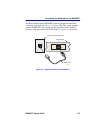
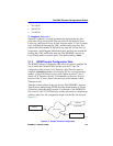
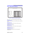
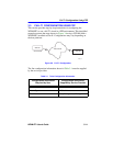
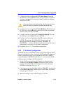
Figure 3-3 shows a sample configuration for three sites. Of the 24
Timeslots, Site #1 uses 16 to communicate with Site #2 and the remaining
8 to communicate with Site #3. This configuration varies tremendously
depending on how the service provider maps out the T1 Timeslots. The
service provider indicates which Timeslots are active.
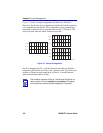
Figure 3-3 Sample Configuration
Site #1 is using the full T1, so all the Timeslots must have an Interface
assignment. Site #2 and Site #3 use only a fraction of the T1, but the total
quantity of Timeslots must match those of Site #1. Unused Timeslots
receive an Interface number of 000.
NOTE
The Interface numbers of Site #1, Site #2 and Site #3 do not
have to match. Only the quantity and position of Timeslots
must match (the service provider assigns the Timeslots).
SITE #2
01-08
09-16
17-24
SITE #3
01-08
09-16
17-24
SITE #1
01-08
09-16
17-24
1482_03
005
005
000
005
005
000
005
005
000
005
005
000
005
005
000
005
005
000
005
005
000
005
005
000
000
000
006
000
000
006
000
000
006
000
000
006
000
000
006
000
000
006
000
000
006
000
000
006
005
005
006
005
005
006
005
005
006
005
005
006
005
005
006
005
005
006
005
005
006
005
005
006