


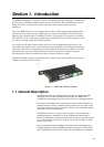


Section 2. Installation
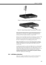
The SDM-CAN can be mounted in a normal card slot of a CR9000 (using optional special end
brackets), on a chassis plate (using the standard brackets supplied) or can be left free-
standing.
CR9000 and CR7 dataloggers require optional SDM connection kits and all dataloggers may
require an upgrade to a version of operating system which supports the SDM-CAN interface.
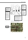
2.1 Address Switch Configuration
Before installing the SDM-CAN, set the SDM address switch to ensure that the
interface has a unique address on the SDM bus, and that the address is set to
match the commands in the datalogger program relevant to each interface.
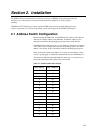
The SDM address switch can be set to 1 of 16 addresses. The factory-set address
is 00. Table 1 shows switch position and the corresponding address. The Base 4
address is also shown, as this is the address entered in the datalogger program.
Please see Section 3 before using address F (33 base 4) as this address is often
used as a ‘group trigger’ to synchronise measurements by several SDM devices.
The switch is positioned on the right-hand side of the case, so you may have to
remove the mounting bracket to gain access to this switch.
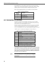
Table 2-1 Switch Position and Addresses
Switch Setting Base 4 Address
0 00
1 01
2 02
3 03
4 10
5 11
6 12
7 13
8 20
9 21
A 22
B 23
C 30
D 31
E 32
F 33
2-1