


Section 3. Programming CR10X, CR7 and CR23X
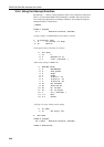
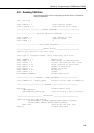
6: 6 Loc [ TC_1 ]
7: 1.0 Mult
8: 0.0 Offset
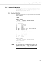
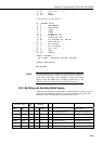
;Transmit Data on to CAN network
13: SDM-CAN (P118)
1: 0 SDM Address
2: 2 Time Quanta
3: 5 Tseg1
4: 2 Tseg2
5: 1 ID Bits 0..10
6: 0 ID Bits 11..23
7: 0 ID Bits 24..28
8: 20 Tx, unsigned int, LSB 1st
9: 1 Start Bit No.
10: 16 No. of Bits
11: 1 No. of Values
12: 6 Loc [ TC_1 ]
13: 1.0 Mult
14: 0.0 Offset
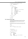
*Table 2 Program
02: 0.0000 Execution Interval (seconds)
*Table 3 Subroutines
End Program
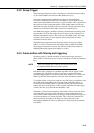
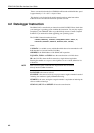
The default setting for the SDM-CAN internal software switches is
0. The switches must be set by using the data type 32 parameter to
enable data transmission. Also remember to check the jumper
settings inside the SDM-CAN if enabling transmission, as the
default setting is for transmission to be disabled in hardware.
NOTE
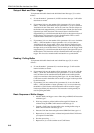
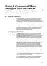
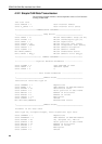
3.5.3 Building and Sending Data Frames
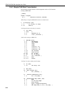
The following table shows the parameters used for the process of using a series of
P118s to build a dataframe and then use a further call with data type set to 26 to
define part of the working buffer as a remote frame response:
Input Loc Value Data
type
Start Bit
nbits
Dec Hex Indexed 64 bit Frame
Un-initialised frame>> 0x12abcdef12345678
170 0xaa 7 5 N 8 Loaded into frame>> 0x0000000000000aa0
1234 0x4d2 13 17 N 16 Ored into frame>> 0x0000000004d20aa0
65535 0xffff 13 31 N 7 Ored into frame>> 0x0000001fc4d20aa0
171 0xab 13 8 Y 8 Ored into frame>> 0xab00001fc4d20aa0
X X 26 28 Y 32 Remote Response Frame>> 0x0ab00001 32 bit frame
3-19