


SDM-CAN CAN-Bus Interface User Guide
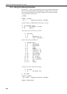
Setup of Mask and Filter / trigger
To implement this buffer function the build data frame Data type (7) is used as
follows:-
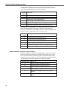
a) If “start bit number” (parameter 9) is NON-zero then data type 7 will build a
data frame as normal.
b) If (parameter 9) is zero, the number of bits (parameter 10) is set to 8 with
index (--) NOT SET and number of bytes (parameter 11) is set to 16 then an
`Include mask’ and `Filter mask’ can be set at run time. The first 8 bytes are
the Include mask mapped directly as a 64 bit frame with the first byte as the
right most byte of the data frame. The second 8 bytes is the Filter mask
mapped directly as a 64 bit frame with the first byte as the right most byte of
the data frame. This instruction will also flush the buffer. This is used to
create the buffer and attach it to a particular ID.
s
c) If (parameter 9) is zero, the number of bits (parameter 10) is set to 8 with the
index (--) SET and number of bytes (parameter 11) is set to 16 then an
`Include mask’ and `Trigger mask’ can be set at run time. The first 8 bytes
are the Include mask mapped directly as a 64 bit frame with the first byte as
the right most byte of the data frame. The second 8 bytes is the Trigger mask
mapped directly as a 64 bit frame with the first byte as the right most byte of
the data frame. This instruction will also flush the buffer and reset ready for
trigger. This is used to create the buffer and attach it to a particular ID.
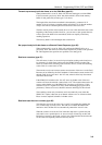
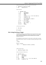
Reading / Polling Buffer
To implement this buffer function the read switch Data type (33) is used as
follows: -
a) If “start bit number” (parameter 9) is zero then data type 33 will read the
internal switches as normal.
b) If (parameter 9) is one, the number of bits (parameter 10) is set to 8 with the
index (--) NOT SET and number of bytes (parameter 11) is set to zero then
one CAN frame will be transferred from the buffer to the working buffer
ready for normal data collection using Data Types 1-6. Also the number of
CAN frames stored in the buffer will be stored in a logger location specified
by this instruction.
c) If (parameter 9) is one, number of bits (parameter 10) is set to 8 with the
index (--) SET and number of bytes (parameter 11) is set to zero then only
the number of CAN frames stored in the buffer will be stored in a logger
location specified by this instruction. This instruction would generally be
used for polling the buffer.
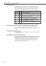
Basic Sequence of Buffer Usage:-
1. Initialise buffer and trigger event or filter using an SDM-CAN instruction
with data type 7.
2. Wait long enough or poll the buffer until enough CAN frames are
collected using an SDM-CAN instruction with data type 33.
3. Transfer a CAN frame from the buffer to the working buffer using an
SDN-CAN instruction with data type 33.
4. Parse the CAN data frame using the normal SDM-CAN data types 1-6.
5. Repeat from (3) until you have collected and parsed all the CAN frames
you require from the buffer.
6. Do other processing ………..
7. Repeat from (1) to collect another set of CAN frames.
3-16