


SDM-CAN CAN-Bus Interface User Guide
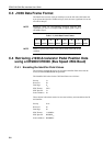
C.3 J1939 Data Frame Format
The Data Frame consists of 8 bytes with byte one at the left side of the frame and
byte eight at the right side. Within each byte, bit 8, the most significant bit is at the
left side of the byte.
Multi-byte values are conventionally displayed with the least
significant byte first. For example LSB of engine speed is Byte 4
and MSB is byte 5.
NOTE
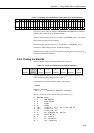
Table C-3 J1939 Data Frame Format
1 2 3 4 5 6 7 8
87654321 87654321 87654321 87654321 87654321 87654321 87654321 87654321
Details of specific data frame values can be found in the SAE J1939
standard.
NOTE
C.4 Retrieving J1939 Accelerator Pedal Position Data
using a CR9000/CR5000 (Bus Speed 250k Baud)
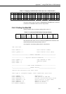
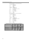
C.4.1 Encoding the Identifier Field Values
The following example shows how to encode the identifier field values into the
format for the CR9000/CR5000 ID parameter.
The identifier field values for the CAN Data Frame are as follows:
Priority 3
10
Reserved 0
10
Data Page 0
10
PDU Format 240
10
PDU Specific 3
10
Source Address 0
10
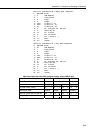
These decimal values then need to be converted to binary and encoded into the 29
bit identifier.
Priority 011
2
Reserved 0
2
Data Page 0
2
PDU Format 11110000
2
PDU Specific 00000011
2
Source Address 00000000
2
C-2