


SDM-CAN CAN-Bus Interface User Guide
If the LED flashes once, the module has passed all power-up tests and should
operate correctly. The other flash sequences are shown below. Problems with the
operating system can normally be fixed by reloading the operating system.
Please contact Campbell Scientific if you are unable to resolve the problem.
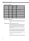
Table 2-2 LED Status Indication
Number of
flashes
Indication
1 SDM-CAN is ok.
2 OS signature bad.
10 OS downloaded has failed.
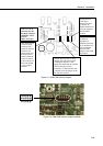
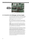
2.4 Connection to CAN-Bus.
The physical connection to the CAN-Bus is achieved by one of two methods
which is by either the 3 way un-pluggable screw terminals or the 9 pin ‘D’ plug
which conforms to CIA draft standard 102 version 2.
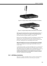
The basic connections of the CAN-Bus to the three-way terminal are CAN High,
CAN Low and 0V ground reference. The 3 way screw terminal is marked as
‘G H L’ on the SDM-CAN case, where G=Ground, H=CAN High, L=CAN Low.
The CIA, 9 pin, ‘D’ connector pin configuration is shown in Table 2-3.
Table 2-3 CIA CAN Connector Pin Connections
Pin Function
1 Reserved, NOT INTERNALLY CONNECTED.
2 CAN Low.
3 CAN Ground.
4 Reserved, NOT INTERNALLY CONNECTED.
5 CAN Shield.
6 CAN Ground.
7 CAN High.
8 Reserved, NOT INTERNALLY CONNECTED.
9 CAN +5volts. Input or output (see text).
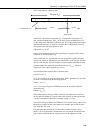
If the SDM-CAN hardware is configured (in either isolated or non-isolated mode)
with the DC-DC converter ON, then Pin 9 of the 9 pin ‘D’ connector will provide
+5V +/-10% at up to 40mA to any external device. If isolation is enabled and the
DC-DC converter is set to OFF then this pin acts as an input for an external power
supply capable of providing +5volts +/-10% at up to 100mA to provide power to
the isolated circuitry of the SDM-CAN.
The 3-way terminal block and CIA connector are connected in
parallel internally and are not two separate connections to different
CAN interfaces.
NOTE
2-6