


7
. Introduction
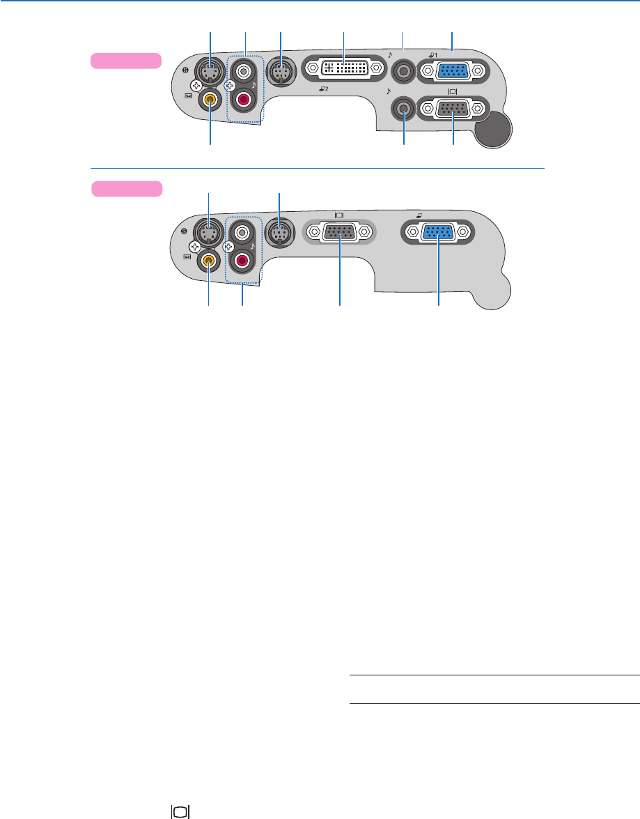
AUDIO IN
AUDIO OUT
S
-
VIDEO
IN
VIDEO
IN
L
AUDIO IN
R
SERVICE PORT
ANALOG IN-1
DIGITAL IN /
ANALOG IN-2
97 3 128
456
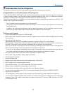
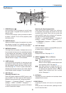
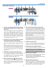
Terminal Panel Features
.
Computer Input Connector [ANALOG IN-] (Computer
Input Connector [ANALOG IN] on LV-7260/LV-X7) (Mini
D-Sub 5 Pin)
Connect your computer or other analog RGB equip-
ment such as IBM compatible or Macintosh com-
puters. Use the supplied VGA cable to connect to
your computer. This also serves as a component
input connector that allows you to connect a com-
ponent video output of component equipment such
as a DVD player. See page 15, 18, 20.
2. Computer 2 Input Connector [DIGITAL IN/ANA
-
LOG IN-2] (DVI-I 29 Pin) (LV-7365/LV-7265)
Connect your computer or other analog RGB equip-
ment such as IBM compatible or Macintosh comput-
ers.
Use the supplied VGA cable to connect to your com-
puter. This also serves as a component input connec-
tor that allows you to connect a component video out-
put of component equipment such as a DVD player.
See page 15, 16.
3.
AUDIO IN Mini Jack (Stereo Mini) (LV-7365/LV-7265)
This is where you connect the audio output from
your computer or DVD player when connected to
the COMPUTER input. A commercially available
audio cable is required. See page 15, 20.
.
Monitor Output Connector [ ] (Mini D-Sub 5 Pin)
You can use this connector to loop your computer im-
age to an external monitor from the RGB input source.
This connector outputs RGB signal in standby
mode. See page 19.
5.
AUDIO OUT Mini Jack (Stereo Mini) (LV-7365/LV-7265)
You can use this jack to output sound from the cur-
rently selected source (COMPUTER, VIDEO or
S-VIDEO). Output sound level can be adjusted in ac-
cordance with the sound level of the internal speaker.
Note that this cannot be used as a headphone jack.
(When audio equipment is connected, the projector
speaker is disabled.)
When a cable mini-plug is inserted into this jack, both the
right and left audio signals are not mixed, but separate.
For example, when a cable mini-plug is inserted into
the left AUDIO IN jack only, only left sound is output.
6. VIDEO IN Connector (RCA)
Connect a VCR, DVD player, laser disc player, or
document camera here to project video. See page 21.
7. S-VIDEO IN Connector (Mini DIN Pin)
Here is where you connect the S-Video input from
an external source like a VCR. See page 21.
NOTE: S-Video provides more vivid color and higher reso-
lution than the traditional composite video format.
8. AUDIO IN Jacks L/R (RCA)
These are your left and right channel audio inputs for
stereo sound from a Video/S-Video source.
These jacks support an analog RGB audio source on
LV-7260/LV-X7. See page 18, 21.
9. SERVICE PORT (Mini DIN 8 Pin)
Use this port to connect a PC or control system to
control the projector via an optional RS-232C serial
cable (LV-CA34). If you are writing your own pro-
gram, typical PC control codes are on page 71.
LV-7365/LV-7265
S
-
VIDEO
IN
VIDEO
IN
L
AUDIO IN
R
SERVICE PORT
ANALOG IN
97
146 8
LV-7260/LV-X7