


20020601
English
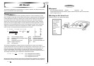
í Equipment
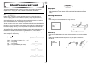
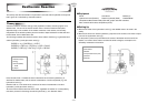
AC Power Supply (Switched) Resistor Capacitor Coil
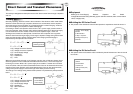
Voltage Measurement Setup (EA-200, graphic scientific calculator, data communication
cable, voltage probe (3))
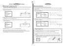
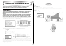
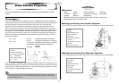
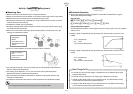
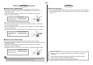
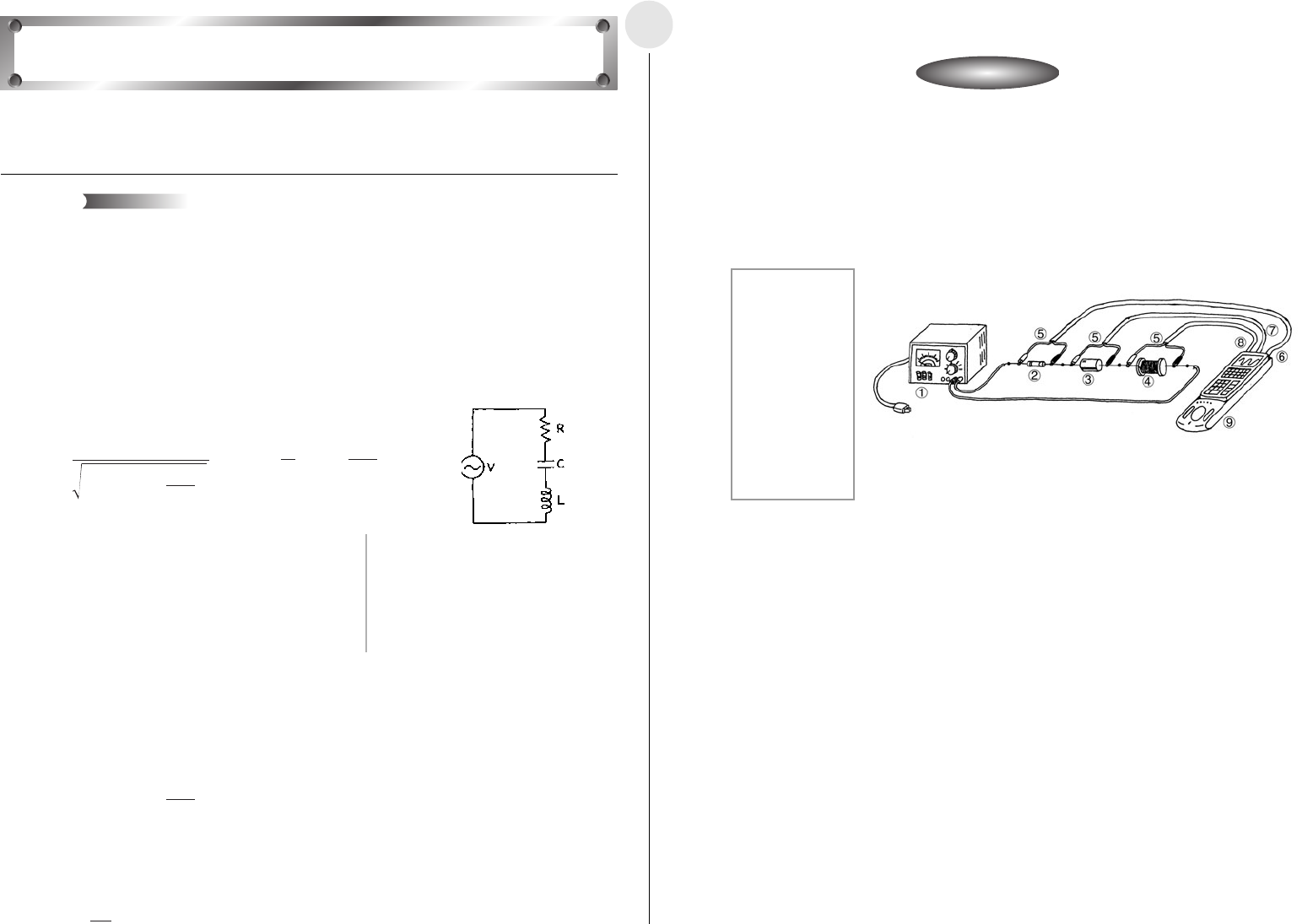
í Building the RCL Series Circuit
u Build a circuit for a 3V, 50Hz power supply.
2-10-1
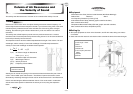
This activity investigates the characteristics of a resistor, capacitor, coil (RCL) series circuit,
which is connected to an AC power supply.
The electrical power sent from power generating stations to homes is alternating current
(AC), not direct current (DC). Though direct current does not alternate with time, alternating
current alternates according to a regular cycle, and this cyclical change can be expressed
as a trigonometric function. When the voltage and frequency of a AC power supply are
defined, the current flowing through the circuit has the same frequency as but a different
phase from the power supply voltage. The phase difference and the magnitude of current
depends on the component parts of the circuit. The voltage and current when a AC power
supply is connected to a series circuit composed of a resistor, capacitor, and coil (RCL
series circuit) can be expressed by the expressions shown below.
V(V) : AC Power Supply Voltage R(Ω):Resistance Value
V
0(V) :
Amplitude of AC Power Supply Voltage
C(F) : Capacitor Capacitance
I(A) : AC Current L(H) : Coil Self-inductance
I
0(A) : Amplitude of AC Current
φ
(rad) : Current Phase Difference
ω
(rad/s): Angular Frequency t(s) : Time
f(Hz) : AC Frequency
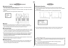
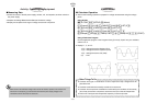
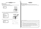
This activity investigates the voltage across the components of a series circuit. When a
current that alternates with time is applied, the voltage across a capacitor and a coil is out of
phase with the power supply voltage by -
π/2 and π/2 respectively. The resistor does not
have this characteristic, and so there is no phase lag. All of this means the peaks and
valleys of the waveforms of the voltage across the components will be in different locations.
The voltage across each of the components is expressed as follows.
V
R(V):Voltage Across the Resistor
V
C(V):Voltage Across the Capacitor
V
L(V) :Voltage Across the Coil
We also know that the maximum current value is achieved using a capacitor-coil combination
that satisfies the conditions shown below. A frequency like this is called a “resonant frequency.”
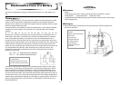
AC Circuit
Theory
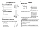
1 3V, 50Hz AC
Power Supply
2 10Ω Resistor
3 100µ F
Capacitor
4 10mH Coil
5 Voltage Probe
6 CH1
7 CH2
8 CH3
9 EA-200
Activity: SetupActivity: Setup
2
=
ω
1
LC
V = V0 cos t I = I0 cos( t – ) = 2πf
I0 = tan =
1
C
φ
φ
ω
ω
ω
R
2
+
(
L –
)
2
1
C
ω
ωω
1
R
ω
(
L –
)
V0
VR = I0R VC = VL = I0L
ω
I0
C
ω