


i4000 - Quad M-module carrier for VMEbus
User Manual Version: 1.2
AcQuisition Technology bv
P.O. Box 627, 5340 AP
Oss, The Netherlands Page 11 of 25
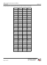
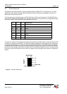
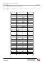
3.2.2. P2 CONNECTOR ASSIGNMENTS (I4000/P2 ONLY)
Peripherals can be connected to M-modules in two ways. On the front of the M-module a 25-pole sub-D
connector (or mechanically equivalent) can be used to connect cables on the front panel of the VMEbus base
board. Alternatively a 24-pole header connector interfaces the I/O signals to the base board where they are
connected to the VMEbus P2 connector.
In 32-bit VMEbus systems the backplane for the P2 connector must either be removed for the i4000 slot or an
i4000 without the P2 connector must be ordered. In that case the peripherals only can be connected to the
M-module up front.
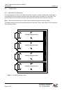
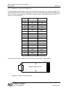
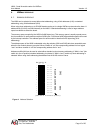
Every M-module has 24 pins of the P2 connector assigned. This way four modules on a base board can use
this I/O path.
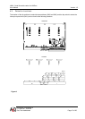
This division into four pads of the P2 connector enables the so called “module connector” to be plugged into
the back of a 96-way shroud, mounted on the “P2-backplane”. On the 96-way connector 3 pins are not used
for every module. Several manufacturers produce these “module connectors”, which can be coded and
sometimes have latches.
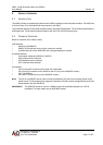
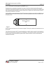
Figure 2
Module component
side
PIN24
PIN1
PIN2