


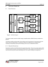
i4000 - Quad M-module carrier for VMEbus
User Manual Version: 1.2
AcQuisition Technology bv
P.O. Box 627, 5340 AP
Oss, The Netherlands Page 13 of 25
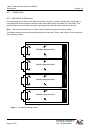
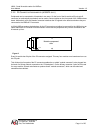
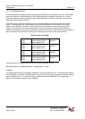
3.2.3. M-MODULE INTERFACE CONNECTOR
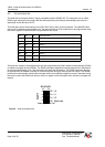
The following table provides signal names for the M-module male connector that is used by the i4000. The
connector consists of two rows of pins labelled rows A and B. The M-module specification also defines a third
row (C). This row is rarely used and not available on the i4000. When an M-module with row A, B and C is
used, row C is left unoccupied.
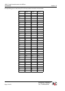
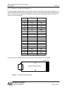
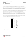
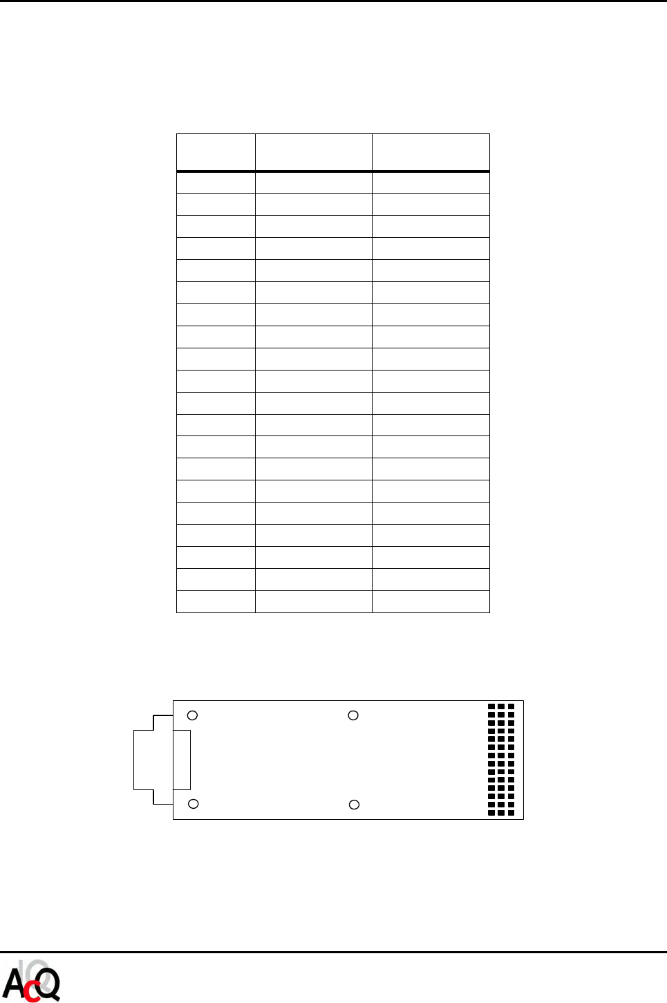
Location of the 40 or 60 pole female header connector on the M-module: (60 pole shown)
Pin
Number
Row A Row B
01 CS* GND
02 A01 +5V
03 A02 +12V
04 A03 -12V
05 A04 GND
06 A05 DREQ*
07 A06 DACK*
08 A07 GND
09 D08 D00
10 D09 D01
11 D10 D02
12 D11 D03
13 D12 D04
14 D13 D05
15 D14 D06
16 D15 D07
17 DS1* DS0*
18 DTACK* WRITE*
19 IACK* IRQ*
20 RESET* SYSCLK
Figure 3 M-module Interface Connector
Module component side
20
1
Row A, B, C