


i4000 - Quad M-module carrier for VMEbus
User Manual Version: 1.2
AcQuisition Technology bv
P.O. Box 627, 5340 AP
Oss, The Netherlands Page 21 of 25
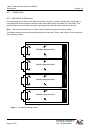
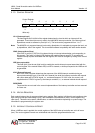
5.1.3. CONTROL REGISTER
L2-L0 (Interrupt level)
The least significant 3-bit field of the register determines the level at which an interrupt will be
generated. These three bits are only used in the i4000/NP2 interrupt controller, if the interrupt level
dipswitches are set to software irq level (all “on”). The level can be programmed from “1 to 7”.
Note: The i4000/P2 only supports interrupt levels set by dipswitches, it is advisable to program the level, set
by dipswitches, also in the register. This to maintain software compatibility with other similar boards.
IRAC (Interrupt Auto-Clear)
If the IRAC is set (bit 3), IRE (bit 4) is cleared during an interrupt acknowledge cycle responding to
this request. This action of clearing IRE disables the module interrupt request. To re-enable the
module interrupt request associated with this register, IRE must be set again by writing to the control
register.
IRE (Interrupt enable)
This field (bit 4) must be set (high level) to enable the module interrupt request associated with the
control register. If the module asserts IRQ, but IRE is cleared, no interrupt request to the VMEbus will
be generated.
X/IN* (External/Internal)
Bit 5 of the control register determines the response of the i4000 interrupt controller during an
interrupt acknowledge cycle. If the X/IN* bit is cleared (low level) the interrupt controller will respond
with vector data and a DTACK* signal, i.e., an internal response. If X/IN* is set, the vector is not
supplied and no DTACK* is given by the interrupt controller, i.e., an external module should respond.
RESERVED
These two bits are not used in the current implementation of the interrupt controller and are reserved
for future use.
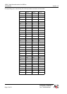
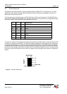
5.1.4. VECTOR REGISTERS
Each module interrupt has its own associated vector register. Each register is 8 bits wide and supplies a data
byte during its interrupt acknowledge cycle, if the associated External/Internal (X/IN*) control register bit is
clear (zero). This data can be status, identification, or address information depending on system usage. The
information is programmed by the system user.
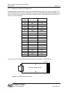
5.1.5. INTERRUPT CONTROLLER RESET
When a VMEbus reset is applied, the control registers of the i4000 interrupt controller are set to all zeros
(low). The vector registers however are uninitialized and should be programmed before use.
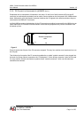
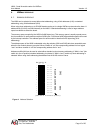
Control Register
76543210
RES RES X/IN IRE IRAC L2 L1 L0
Reset:
uuuuuuuu
Write only