


i4000 - Quad M-module carrier for VMEbus
User Manual Version: 1.2
AcQuisition Technology bv
P.O. Box 627, 5340 AP
Page 18 of 25 Oss, The Netherlands
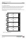
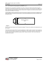
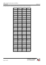
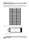
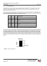
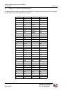
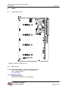
4.4. VMEBUS P1 CONNECTOR ASSIGNMENTS
The following table provides signal names for the VMEbus P1 connector as used by the i4000. The connector
consists of three rows of pins labelled rows A, B and C.
Pin Row A Row B Row C
01 D00 D08
02 D01 D09
03 D02 D10
04 D03 BG0IN* D11
05 D04 BG0OUT* D12
06 D05 BG1IN* D13
07 D06 BG1OUT* D14
08 D07 BG2IN* D15
09 GND BG2OUT* GND
10 SYSCLK BG3IN*
11 GND BG3OUT*
12 DS1* RESET*
13 DS0* LWORD*
14 WRITE* AM5
15 GND A23
16 DTACK* A22
17 GND A21
18 AS* A20
19 GND A19
20 IACK* GND A18
21 IACKIN* A17
22 IACKOUT* A16
23 AM4 GND A15
24 A07 IRQ7* A14
25 A06 IRQ6* A13
26 A05 IRQ5* A12
27 A04 IRQ4* A11
28 A03 IRQ3* A10
29 A02 IRQ2* A09
30 A01 IRQ1* A08
31 -12V +12V
32 +5V +5V +5V