Page 9For technical questions, please call 1-800-444-3353.SKU 93765
OPERATION
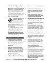
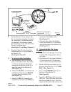
When connecting the Camera (1) 1.
to the Monitor (2) the power must
be off or both units may be dam-
aged.
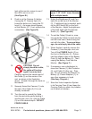
IMPORTANT: 2. To avoid damage to
the Camera (1) and/or Cable (3) use
caution when inserting or retracting
the equipment in pipes, ducts, etc.
Avoid sharp corners and edges; the
cable can kink and break internally if
bent sharply. If necessary, insert the
Ball Protector (9) over the Camera for
added protection. The Ball Protec-
tor may also help keep the Camera
clean.
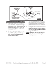
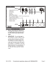
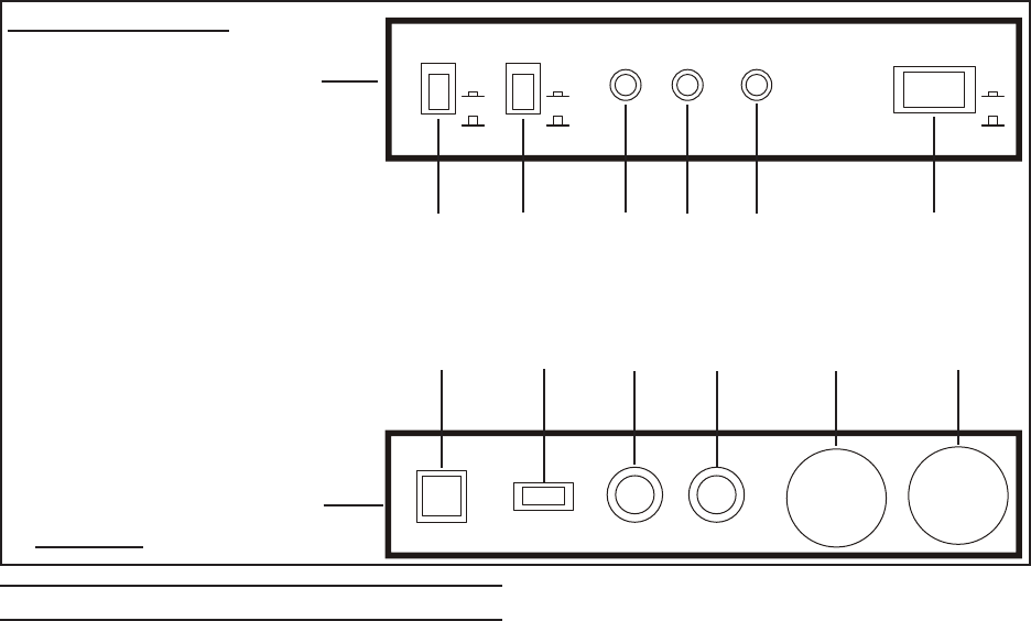
Monitor Controls:
A. Camera Selection Switch
B. LED Switch
C. LED Dimmer
D. Contrast
E. Brightness
F. Monitor Power Switch
G. DC 12 Volt-Input (Plug in 12VDC Power System Here)
H. External Video-In Switch
I. Video-Out (Used to Record to a VCR)
J. External Video-Input
K. Camera 1 Input
L. Camera 2 Input
Figure B
A B C
D
E F
CAMERA
LED DIMMER CONT. BRIGHT. POWER
C1
C2
ON
OFF
MIN. MAX.
ON
OFF
MONITOR
(FRONT VIEW)
G H I
J
K
L
MONITOR
(BACK VIEW)
DC 12 VOLT
INPUT
VCR/CAMERA
VIDEO
OUT
VIDEO
IN
C1
C2


