


1-6
Cisco Aironet 1240AG Series Access Point Hardware Installation Guide
OL-8371-05
Chapter 1 Overview
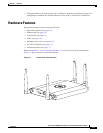
Hardware Features
LEDs
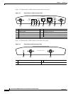
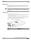
The access point has three LEDs to indicate Ethernet activity, radio activity, and status indications (refer
to the “Checking the Lightweight Access Point LEDs” section on page 3-2 or the “Checking the
Lightweight Access Point LEDs” section on page 4-3 for additional information). Figure 1-2 shows the
location of the LEDs.
• The Status LED provides general operating status and error indications.
• The Ethernet LED signals Ethernet traffic on the wired Ethernet LAN and provides Ethernet error
indications.
• The Radio LED signals that wireless packets are being transmitted or received over the radio
interface and provides radio error indications.
Power Sources
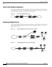
The access point can receive power from an external power module or from inline power using the
Ethernet cable. The access point supports the IEEE 802.3af inline power standard and Cisco CDP Power
Negotiation. Using inline power, you do not need to run a power cord to the access point because power
is supplied over the Ethernet cable.
Warning
This product must be connected to a Power over Ethernet (PoE) IEEE 802.3af compliant power source
or an IEC60950 compliant limited power source.
Statement 353
Caution Be careful when handling the access point; the bottom plate might be hot.
The access point supports the following power sources:
• Power module
• Inline power:
–
Cisco Aironet Power Injector (AIR-PWRINJ3 or AIR-PWRINJ-FIB)
–
An inline power capable switch, such as the Cisco Catalyst 3550 PWR XL, 3560-48PS,
3570-48PS, 4500 with 802.3AF PoE module, or the 6500 with 802.3AF PoE module
–
Other inline power switches supporting the IEEE 802.3af inline power standard
Note Some switches and patch panels might not provide enough power to operate the access point with both
2.4-GHz and 5-GHz radios. At power-up, if the access point is unable to determine that the power source
can supply sufficient power, the access point automatically deactivates both radios to prevent an
over-current condition. The access point also activates a Status LED low power error indication and
creates an error log entry (refer to the “Checking the Lightweight Access Point LEDs” section on
page 3-2 and the “Checking Basic Settings” section on page 3-3).