


2-20
Cisco Aironet 1240AG Series Access Point Hardware Installation Guide
OL-8371-05
Chapter 2 Installing the Access Point
Connecting the Ethernet and Power Cables
Connecting the Ethernet and Power Cables
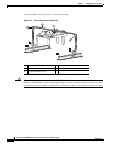
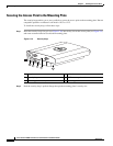
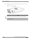
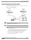
The access point receives power through the Ethernet cable or an external power module. Figure 2-12
shows the power options for the access point.
Figure 2-12 Access Point Power Options
Warning
This product must be connected to a Power over Ethernet (PoE) IEEE 802.3af compliant power source
or an IEC60950 compliant limited power source.
Statement 353
Caution This product and all interconnected equipment must be installed indoors within the same building,
including the associated LAN connections (as defined by Environment A of the IEEE 802.3af standard).
The access point power options:
• Option 1—Switches with sufficient inline power:
–
An inline power capable switch, such as the Cisco Catalyst 3550 PWR XL, 3560-48PS,
3750-48PS, 4500 with 802.3AF PoE module, or the 6500 with 802.3AF PoE module
–
Other inline power switches supporting the IEEE 802.3af inline power standard
• Option 2—Switches without sufficient inline power can use the power injector:
–
Cisco Aironet Power Injector (AIR-PWRINJ3 or AIR-PWRINJ-FIB)
• Option 3—Local power using the power module
Power
cord
Universal
power supply
S
Y
S
T
RPS
DUP
LX
MODE
SP
E
ED
UT
IL
S
TA
T
1
2
3
4
5
6
7
8
9
10
11
12
13
14
15
16
17
18
19
20
21
22
23
24
23
24
10Base-T / 100Base-TX
100Base-FX
Catalyst 2950
S
ERIE
S
SYST
RP
S
D
UP
LX
MO
DE
S
PEED
UTI
L
STAT
1
2
3
4
5
6
7
8
9
10
11
12
13
14
15
16
17
18
19
20
21
22
23
24
23
24
10Base-T / 100Base-TX
100Base-FX
Catalyst 2950
SERIES
T
O
AP/
B
RI
DGE
TO
NETWORK
Switch with
inline power
Power injector
Access Point
Switch without
inline power
Option 1 Option 2
Option 3
135476