


7
Installing and Formatting Cisco 2691, Cisco 3631 and Cisco 3700 CompactFlash Memory Cards
78-13892-03
March 2002
Internal CompactFlash Memory Card Installation and Removal
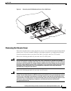
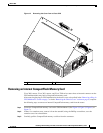
Removing a Plug-in CPU/Mainboard
This section describes how to access a CompactFlash memory card mounted on a CPU/mainboard that
slides out of the chassis. You need a number 2 Phillips or flat-blade screwdriver to complete this
procedure.
Cisco 3745 routers have a plug-in CPU/mainboard.
Observe the following precaution if your router uses AC power:
Warning
Do not touch the power supply when the power cord is connected. For systems with a power
switch, line voltages are present within the power supply even when the power switch is OFF and
the power cord is connected. For systems without a power switch, line voltages are present within
the power supply when the power cord is connected. To see translations of the various warnings
that appear in this publication, refer to the Regulatory Compliance and Safety Information
document that accompanied this device.
Observe the following precaution if your router uses DC power:
Warning
Before performing any of the following procedures, ensure that power is removed from the DC
circuit. To ensure that all power is OFF, locate the circuit breaker on the panel board that services
the DC circuit, switch the circuit breaker to the OFF position, and tape the switch handle of the
circuit breaker in the OFF position. To see translations of the various warnings that appear in this
publication, refer to the Regulatory Compliance and Safety Information document that
accompanied this device.
Complete the following procedure to remove the CPU/mainboard from the chassis:
Step 1 Power OFF the router. However, to channel ESD voltages to ground, do not unplug the power cable.
Caution The Cisco 3745 can have more than one power supply. Be sure that all power supplies are powered
OFF, and that the LEDs are all dark.
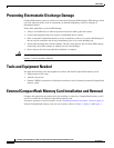
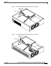
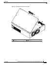
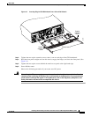
Step 2 Place the router on a flat surface so that the front panel is facing you, and open the small access panel at
the right-hand edge of the front panel.
Step 3 Loosen the two captive screws located behind the access panel. (See Figure 8.)
Step 4 Open the front panel to the straight-out position, and lift it off its hinges. (See Figure 8.)
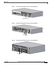
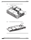
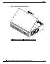
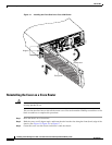
Step 5 Loosen the captive retention screws; there is one at each side of the CPU/mainboard. (See Figure 9.)
Step 6 Pull the ejector levers at both sides, and carefully pull the CPU/mainboard straight out of the chassis.
Place it on an antistatic surface. (See Figure 9.)
Step 7 When you are ready to reinstall the CPU/mainboard, refer to the “Reinstalling a Plug-in
CPU/Mainboard” section on page 14.