


15
Cisco 2700 Series Wireless Location Appliance Deployment Guide
OL-8478-01
Deployment and Design Requirements
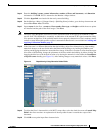
Step 14 Enter the building’s name, contact information, number of floors and basements, and dimension
information. Click OK. WCS is returned to the Monitor > Maps window.
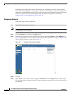
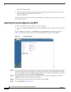
Step 15 Click the hyperlink associated with the newly created building.
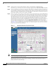
Step 16 On the Monitor > Maps > [Campus Name] > [Building Name] window, go to the drop-down menu and
choose New Floor Area. Click Go.
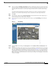
Step 17 Input a name for the floor, a contact, a floor number, floor type, and height at which the access points
are installed and the path of the floor image. Click Next.
Note The Floor Type (RF Model) field allows for the characterization of the type of environment on that
specific floor. This RF Model is essentially an indication of the amount of RF signal attenuation likely
to be present on that floor. If the available models do not properly characterize a floor's makeup, details
on how to create RF models specific to a floor's attenuation characteristics are available in Creating and
Applying Calibration Models, page 17.
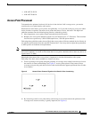
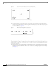
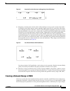
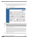
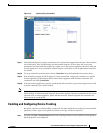
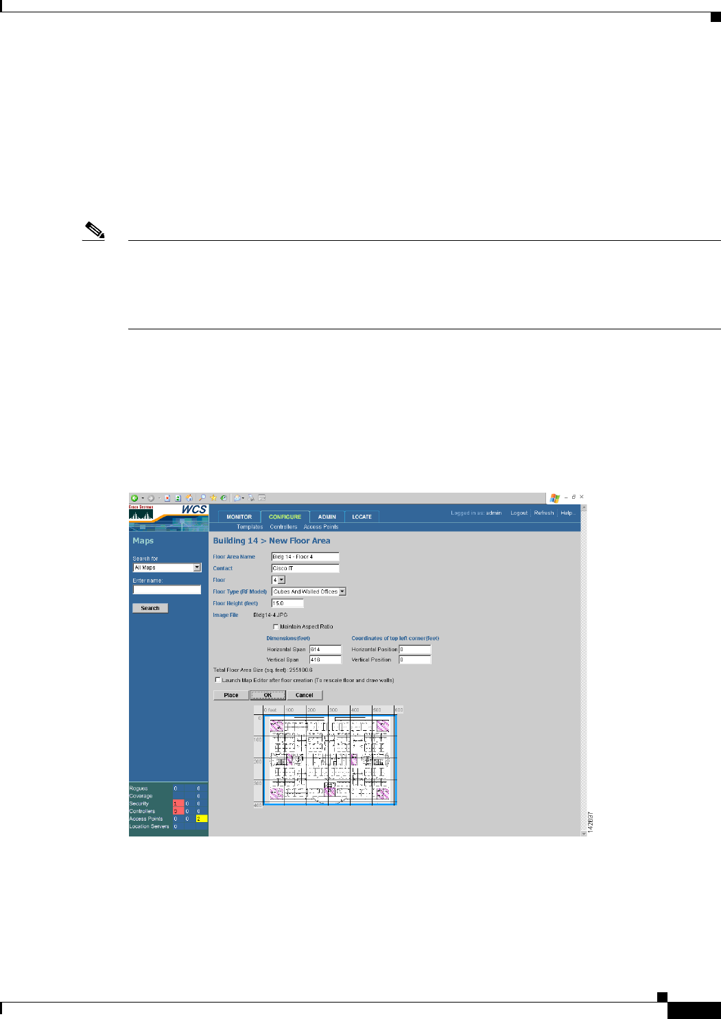
Step 18 If the floor area is a different dimension than the building, adjust floor dimensions by either making
numerical changes to the text fields under the Dimensions heading or by holding the Ctrl key and
clicking and dragging the blue box around the floor image. If the floor's location is offset from the upper
left corner of the building, change the placement of the floor within the building by either clicking and
dragging the blue box to the desired location or by altering the numerical values under the Coordinates
of top left corner heading (see Figure 14). After making changes to any numerical values, click Place.
Figure 14 Repositioning Using Numerical Value Fields
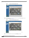
Step 19
To adjust the floor’s characteristics with WCS’s map editor, select the check box next to Launch Map
Editor after floor creation. An explanation of the map editor feature is outside the scope of this
document.
Step 20 Click OK to accept the input floor characteristics.