


17
Cisco 2700 Series Wireless Location Appliance Deployment Guide
OL-8478-01
Deployment and Design Requirements
Creating and Applying Calibration Models
If the provided RF models do not sufficiently characterize the floor layout, you can create a calibration
model that is applied to the floor and better represents the attenuation characteristics of that floor. In
environments where many floors share common attenuation characteristics (such as in a library), one
calibration model can be created and then applied to all similar floors.
Use a laptop or other wireless device to perform the calibration process.
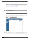
Step 1 Navigate to Monitor > Maps and choose RF Calibration Models from the drop-down menu in the
upper right. Click Go.
Step 2 Choose Create New Model from the drop-down menu in the upper right.Click Go.
Step 3 Assign a name to the model and click OK.
Step 4 The new model appears along with the other RF calibration models but its status is listed as Not Yet
Calibrated. To start the calibration process, click on the hyperlink associated with the new model name.
A new window appears which indicates the details of the new model. In th upper right-hand corner,
choose Add Data Points from the drop-down menu and click Go.
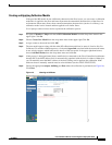
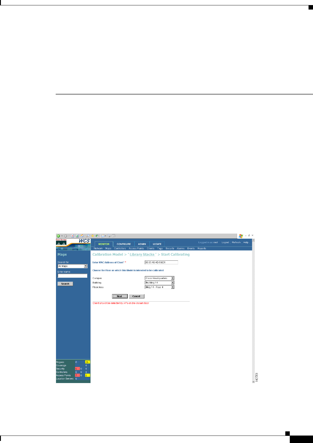
Step 5 If this process is being performed from a mobile device connected to the Cisco Centralized architecture
through WCS, the MAC address field is automatically populated with the device’s address. Otherwise,
you can manually enter the MAC address of the device being used to perform the calibration. MAC
addresses that are manually entered must be colon delimited (such as FF:FF:FF:FF:FF:FF).
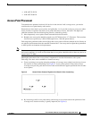
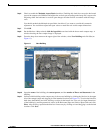
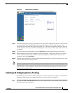
Step 6 Choose the appropriate campus, building, and floor where the calibration is performed (see Figure 16).
Click Next.
Figure 16 Starting to Calibrate