


CHAPTER
2-1
Installation and Upgrade Guide for Cisco Unified Videoconferencing 3515 MCU12 and MCU24 Release 5.1
OL-11897-01
2
Setting Up Your Cisco Unified
Videoconferencing 3515 MCU
This section describes the following topics:
• Physical Description of the Cisco Unified Videoconferencing 3515 MCU, page 2-1
• Preparing to Install the 3515 MCU, page 2-2
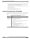
• Verifying the Package Contents of the 3515 MCU, page 2-3
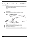
• Mounting the Cisco Unified Videoconferencing 3515 MCU Unit in a 19-inch Rack, page 2-4
• Cisco Unified Videoconferencing 3515 MCU Unit Initial Configuration, page 2-5
• Video Processing Module Initial Configuration for the 3515 MCU, page 2-8
• Managing and Monitoring the Cisco Unified Videoconferencing 3515 MCU Unit, page 2-13
• Accessing the Cisco Unified Videoconferencing 3515 MCU Administrator Interface, page 2-14
• Registering the Online Help for the 3515 MCU, page 2-15
Physical Description of the Cisco Unified
Videoconferencing 3515 MCU
Each Cisco Unified Videoconferencing 3515 MCU unit internally contains two cards:
• Signaling and audio card (MCU—the upper card)
• Video processing card (EMP—the lower card)
The two cards work together to perform audio and videoconferencing, but each card requires a unique
IP address. The cards communicate with each other using IP as the backbone.
Note For correct operation, the EMP card must register with the MCU.
This section provides a physical description of the Cisco Unified Videoconferencing 3515 MCU12 and
Cisco Unified Videoconferencing 3515 MCU24 units.
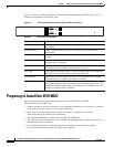
The Cisco Unified Videoconferencing 3515 MCU unit has a 10/100BaseT Ethernet port on the front
panel that uses an RJ-45 connector to connect to the network. There is an asynchronous, 9-pin serial-port
that you can use with a hyperterminal program to configure and monitor the module.