


2-2
Installation and Upgrade Guide for Cisco Unified Videoconferencing 3515 MCU12 and MCU24 Release 5.1
OL-11897-01
Chapter 2 Setting Up Your Cisco Unified Videoconferencing 3515 MCU
Preparing to Install the 3515 MCU
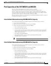
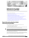
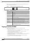
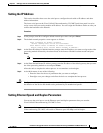
Figure 2-1 shows the front panel of the Cisco Unified Videoconferencing 3515 MCU unit. Table 2-1
describes the components of the front panel.
Figure 2-1 Cisco Unified Videoconferencing 3515 MCU Front Panel
Preparing to Install the 3515 MCU
This section describes the installation requirements for installing the Cisco Unified
Videoconferencing 3515 MCU unit.
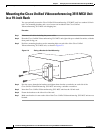
• Proper clearance at the sides of the unit to allow adequate ventilation, and at least 20 cm clearance
at the back of the unit to allow access to cable connections
• A PC with a serial port and terminal emulation software to assign the Cisco Unified
Videoconferencing 3515 MCU unit an IP address
• Two dedicated IP addresses—one each for the MCU and EMP units
• The IP address of the router that the Cisco Unified Videoconferencing 3515 MCU unit will use to
communicate across the network
• For an H.323 environment, IP address of the H.323 gatekeeper with which you want the
Cisco Unified Videoconferencing 3515 MCU unit to register
Table 2-1 Front Panel Components
Component Description
10/100 BaseT connector An RJ-45 connector that provides the primary Ethernet connection for the IP
network port.
Serial connector A DB-9 connector that allows you to connect a PC terminal for local
configuration.
RST button Allows you to reset the Cisco Unified Videoconferencing 3515 MCU unit
manually.
GK Reg and MC LEDs Lights green when the Cisco Unified Videoconferencing 3515 MCU unit is
registered with a gatekeeper.
CPU High LED Lights green when more than 50% of the Cisco Unified
Videoconferencing 3515 MCU unit resources are in use.
ACT LED Lights green to indicate that there is at least one currently active conference
on the Cisco Unified Videoconferencing 3515 MCU unit.
ALARM LED Lights green to indicate that an error has occurred and the Cisco Unified
Videoconferencing 3515 MCU unit requires resetting.
10/100 BaseT LEDs The top part of the 10/100 BaseT connector contains two LED indicators.
The left-hand LED lights green when the local IP network link is active. The
right-hand LED lights green if the connection speed is 100 Mbps, and is off
when the connection speed is 10 Mbps.
10/100 Base T
SERIAL
RST
ACTALARM
CPU HightGK Reg
157265
10/100 Base T
SERIAL
RST
ACTALARM
CPU HightMC
PWR