


1-12
Catalyst 3560-C and 2960-C Switch Hardware Installation Guide
OL-23803-02
Chapter 1 Product Overview
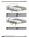
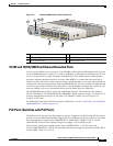
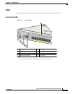
Front Panel
System LED
Console LEDs
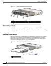
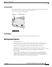
The console LEDs show which console port is in use. See Figure 1-1 and Figure 1-2 for the LED
locations.
If you connect a cable to a console port, the switch automatically uses that port for console
communication. If you connect two console cables, the USB-mini console port has priority.
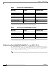
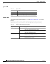
Table 1-4 System LED
Color System Status
Off System is not powered on.
Green System is operating normally.
Amber System is receiving power but is not operating properly.
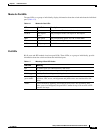
Table 1-5 RJ-45 and USB-Mini Console Port LEDs
LED Color Description
RJ-45 console port Green RJ-45 console port is active.
USB-mini console port LED is not active.
Off Port is not active.
USB-mini console port is active.
USB-mini console port Green USB-mini console port is active.
RJ-45 console port LED is not active.
Off Port is not active.
RJ-45 console port is active.