


B-5
Catalyst 3560-C and 2960-C Switch Hardware Installation Guide
OL-23803-02
Appendix B Connector and Cable Specifications
Cables and Adapters
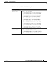
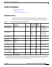
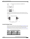
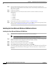
Figure B-8 Four Twisted-Pair Crossover Cable Schematics for 1000BASE-T Ports
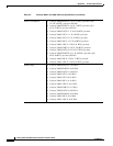
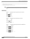
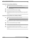
To identify a crossover cable, hold the cable ends side-by-side, with the tab at the back. The wire
connected to pin 1 on the left end should be the same color as the wire connected to pin 3 on the right
end. The wire connected to pin 2 on the left end should be the same color as the wire connected to pin 6
on the right end.
Figure B-9 Identifying a Crossover Cable
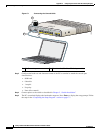
Console Port Adapter Pinouts
The console port uses an 8-pin RJ-45 connector, which is described in Table B-2 and Table B-3. If you
did not order a console cable, you need to provide an RJ-45-to-DB-9 adapter cable to connect the switch
console port to a PC console port. You need to provide an RJ-45-to-DB-25 female DTE adapter if you
want to connect the switch console port to a terminal. You can order an adapter (part number
ACS-DSBUASYN=). For console port and adapter pinout information, see Table B-2 and Table B-3.
Table B-2 lists the pinouts for the console port, the RJ-45-to-DB-9 adapter cable, and the console device.
1 TP0+
2 TP0-
3 TP1+
6 TP1-
1 TP0+
Switch Switch
2 TP0-
3 TP1+
6 TP1-
4 TP2+
5 TP2-
7 TP3+
8 TP3-
4 TP2+
5 TP2-
7 TP3+
8 TP3-
65274
Pin 1
Pin 2
273807
Pin 6
Pin 3
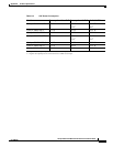
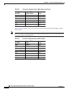
Table B-2 Console Port Signaling Using a DB-9 Adapter
Switch Console
Port (DTE)
RJ-45-to-DB-9
Terminal Adapter
Console
Device
Signal DB-9 Pin Signal
RTS 8 CTS
DTR 6 DSR