


11
Installing and Upgrading Fans in Cisco 3725 Series Routers
78-18564-01
Replacing the Cisco 3725 System Fan
Warning
Network hazardous voltages are present in the BRI cable. If you detach the BRI cable, detach the end
away from the router first to avoid possible electric shock. Network hazardous voltages also are
present on the system card in the area of the BRI port (RJ-45 connector), regardless of when power is
turned off.
Replacing the Cisco 3725 System Fan
The system fan and cabling for the Cisco 3725 router are contained inside the chassis. To replace the
system fan, complete these procedures:
• Removing the Router Cover, page 11
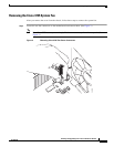
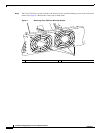
• Removing the Cisco 3725 System Fan, page 13
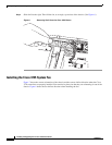
• Installing the Cisco 3725 System Fan, page 16
• Replacing the Router Cover, page 21
• Obtaining Documentation, Obtaining Support, and Security Guidelines, page 23
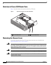
Removing the Router Cover
To access the Cisco 3725 system fan, you must first remove the chassis cover. Follow these steps:
Step 1 Turn off power to the router.
Warning
Before working on a chassis or working near power supplies, unplug the power cord on AC units;
disconnect the power at the circuit breaker on DC units.
Step 2 Remove all network interface cables from the back panel.
Step 3 Remove the power cord.
Warning
When installing the unit, always make the ground connection first and disconnect it last.
Step 4 Place the router so that the back panel is closest to you. Remove the six screws on the top of the cover.
Set the screws aside in a safe place.
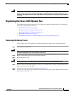
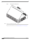
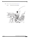
Step 5 Lift the front edge of the cover. (See number 1 in Figure 2.)
Step 6 Slide the cover toward the right until the metal tabs on the back edge separate from the chassis bottom.
(See number 2 in Figure 2.)