


3-25
Catalyst 4500 Series Switches Installation Guide
78-14409-08
Chapter 3 Installing the Switch in a Rack
System Ground Connection Guidelines
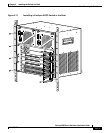
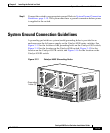
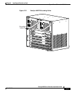
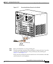
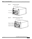
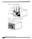
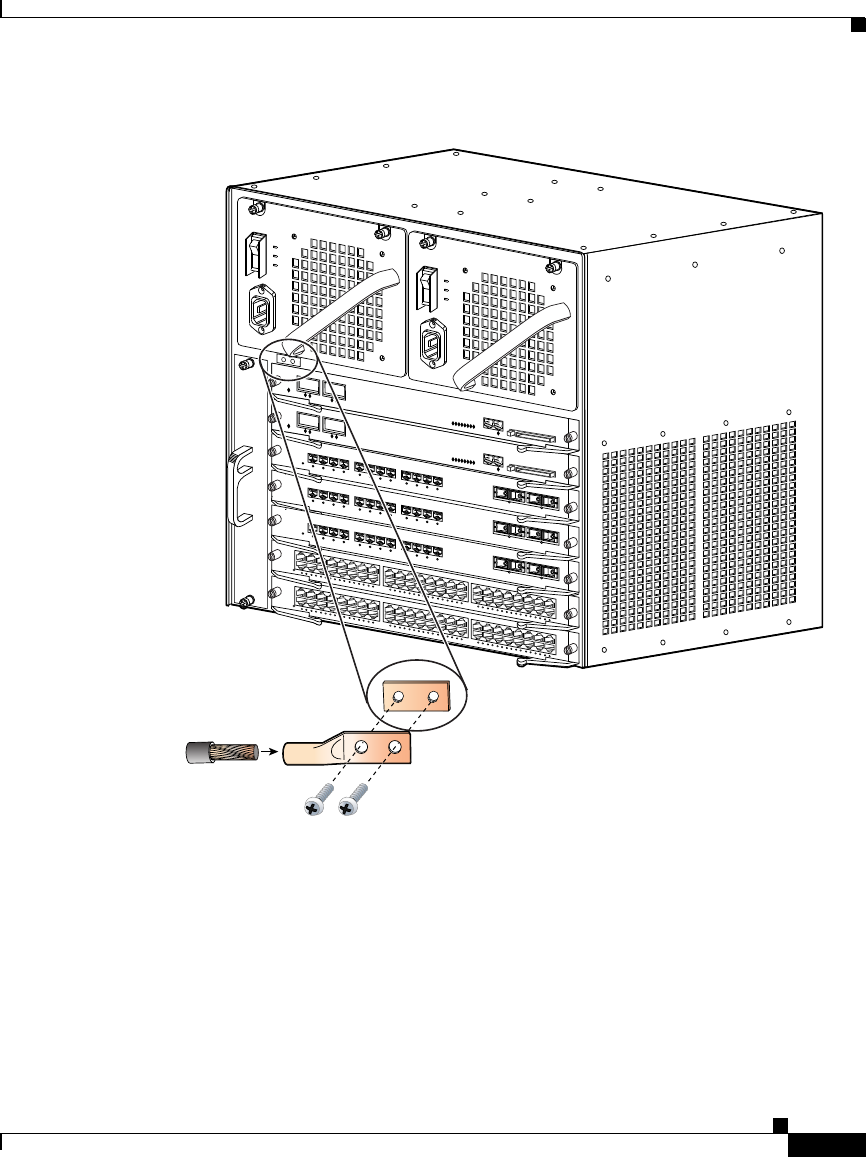
Figure 3-17 Connecting System Ground on the Switch
Step 5 Remove the label that covers the grounding pad.
Step 6 Place the grounding lug against the grounding pad, aligning the holes. Insert the
two M4 screws through the holes in the grounding lug and grounding pad
(
Figure 3-15 and Figure 3-17).
Ensure that the grounding lug and the attached wire will not interfere with other
switch hardware or rack equipment.
79482
WS-X4448-GB-RJ45
S
T
A
T
U
S
1
2
1
1
1
0
9
8
7
6
5
4
3
2
1
1
4
1
3
1
6
1
5
2
8
2
7
2
6
2
5
2
4
2
3
2
2
2
1
2
0
1
9
1
8
1
7
3
0
2
9
3
2
3
1
4
4
4
3
4
2
4
1
4
0
3
9
3
8
3
7
3
6
3
5
3
4
3
3
4
6
4
5
4
8
4
7
1
0
/
1
0
0
B
A
S
E
-
T
X
E
T
H
E
R
N
E
T
M
U
L
T
I
-
S
P
E
E
D
G
I
G
A
B
I
T
E
T
H
E
R
N
E
T
S
W
I
T
C
H
I
N
G
M
O
D
U
L
E
WS-X4448-GB-RJ45
S
T
A
TU
S
1
2
1
1
1
0
9
8
7
6
5
4
3
2
1
1
4
1
3
1
6
1
5
2
8
2
7
2
6
2
5
2
4
2
3
2
2
2
1
2
0
1
9
1
8
1
7
3
0
2
9
3
2
3
1
4
4
4
3
4
2
4
1
4
0
3
9
3
8
3
7
3
6
3
5
3
4
3
3
4
6
4
5
4
8
4
7
1
0
/
1
0
0
B
A
S
E
-
T
X
E
T
H
E
R
N
E
T
M
U
L
T
I
-
S
P
E
E
D
G
I
G
A
B
I
T
E
T
H
E
R
N
E
T
S
W
I
T
C
H
I
N
G
M
O
D
U
L
E
1
STA
TU
S
W
S-X
44
12-2
GB-T
X
2
3
4
5
6
7
8
9
1
0
1
1
1
2
1
7
1
STAT
US
W
S
-X
4412-2G
B
-T
X
2
3
4
5
6
7
8
9
1
0
1
1
1
2
1
7
1
S
TA
TUS
W
S-X4412-2G
B-TX
2
3
4
5
6
7
8
9
1
0
1
1
1
2
1
7
UPLINK
UPLIN
K
CONSOLE
10/100
BASE-TX
STATUS
U
P
L
IN
K
U
P
L
IN
K
CONSOLE
10/100
BASE-TX
STATUS
Grounding
pad
Grounding lug
Wire
Screws (M4)