


4-17
Catalyst 4500 Series Switches Installation Guide
78-14409-08
Chapter 4 Removing and Replacing FRUs
Removing and Replacing the Power Supply
Follow these steps to install a DC-input power supply, connect it to a power
source, and verify its operation:
Step 1 Verify that power is off to the DC circuit or circuits on the power supply you are
installing.
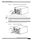
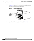
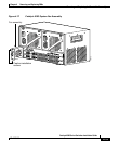
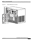
Step 2 Grasp the power supply handle with one hand. Place your other hand underneath
it as you slowly insert the power supply into the bay (as shown earlier in
Figure 4-16).
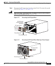
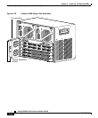
Step 3 Using a screwdriver, tighten the captive screws on the power supply
(see
Figure 4-15).
Step 4 Before you connect the power supply to a power source, ensure that all site power
and grounding requirements have been met.
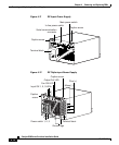
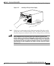
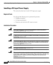
Step 5 Connect the DC-input wires to the power supply terminal block. The proper
wiring sequence is ground to ground, positive to positive, and negative to negative
(see
Figure 4-13 or Figure 4-14 depending on your installation).
The 1400W triple-input power supply has two grounding posts; use the one that
is most convenient for your installation.
Warning
When installing or replacing the unit, the ground connection must always be
made first and disconnected last.
Statement 1046
Step 6 Replace the terminal cover.
Step 7 Connect the other end of the power cords to a DC-power input source.
Caution In a system with multiple power supplies or a single triple-input power supply,
connect each power supply to a separate DC power source. In the event of a power
source failure, if the second source is still available, it can maintain maximum
overcurrent protection for each power connection.