


1-43
Catalyst 4500 Series Switches Installation Guide
78-14409-08
Chapter 1 Product Overview
System Architecture
System Architecture
This section describes the interaction between the various system components of
Catalyst 4500 series switches. A Catalyst 4503 only is shown in the examples.
Power Flow
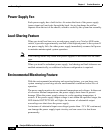
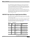
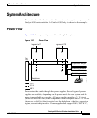
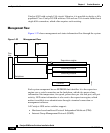
Figure 1-21 shows power ingress and flow through the system.
Figure 1-21 Power Flow
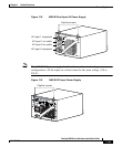
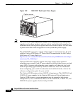
Power enters the switch through the power supplies. Several types of power
supplies are available, depending on the power needs for your system and the
power type available on your site. All power supplies provide a 3.3 V circuit
(shown as a dash-dot line) to the components on the backplane and a 12 V circuit
(shown as a solid line) that is carried over the backplane to the fans, supervisor
engine, and switching modules. Power supplies that support PoE (1300 W AC,
Ingress to PS Ingress to PS
IP
Backplane
PS1 PS2
Fan
tray
120919
Supervisor engine
Switching module
Switching module
12 V
3.3 V
48 V