


Chapter 2 Site Planning
Grounding Requirements
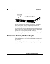
2-6
Catalyst 4900 Series Switch Installation Guide
78-18039-02
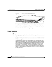
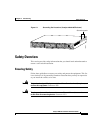
Grounding Requirements
Grounding is recommended on all AC or DC installations, using only approved
copper connectors. Attach the provided two hole ground lug to the chassis using
M4x 8mm bolts and then to the central office (CO) or other interior ground system
with number 6
AWG wire. The grounding connectors are on the right side of the
chassis, and either one may be used. (See
Figure 2-1.)
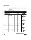
Italy CAB-C2316-C15-IT=
(was CAB-7ACI=)
8.2 ft (2.5 m) 250 VAC, 16 A 1/3/16 CEI 23-16
United
Kingdom
CAB-BS1363-C15-UK=
(was CAB-7ACU=)
8.2 ft (2.5 m) 250 VAC, 13 A BS 89/13
BS 1363/A
Argentina CAB-IR2073-C15-AR=
(was CAB-7KACR=)
8.2 ft (2.5 m) 250 VAC, 10 A IRAM 2073
South Africa,
India
CAB-BS546-C15-SA=
(was CAB-7KACSA=)
8.2 ft (2.5 m) 250 VAC, 10 A BS 546
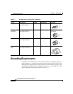
Table 2-1 AC-Input Power Cord Options (continued)
Locale Part Number Length Plug Rating Plug Type
120358
120359
120356
203795