


Chapter 3 Installing the Switch
Rack-Mounting the Switch
3-2
Catalyst 4900 Series Switch Installation Guide
78-18039-02
To verify the contents of the shipping container follow these steps:
Step 1 Compare the contents of the accessories kit to the packing slip. Verify that you
received all listed equipment, which should include the following:
• Switch hardware and software documentation, if ordered
• Optional equipment that you ordered, such as network interface cables,
transceivers, or special connectors
Step 2 To begin installation, proceed to the “Rack-Mounting the Switch” section on
page 3-2.
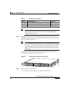
Rack-Mounting the Switch
A standard rack-mount kit is included for mounting the switch in a standard
19-inch (48.3
cm) equipment rack. A standard equipment rack has two
unobstructed outer posts, a minimum depth between the front and rear mounting
posts of 19.25
inches (48.9 cm), and a maximum depth of 32 inches (81.3 cm).
This kit is not suitable for racks with obstructions (such as a power strip) that
could impair access to the switch.
Caution Before installing the chassis in a rack, read the “Site Environmental
Requirements” section on page 2-1 to familiarize yourself with the proper site and
environmental conditions. Failure to read and follow these guidelines could lead
to an unsuccessful installation and possible damage to the system and
components.
Caution This unit is meant to be rack-mounted, and is not intended to bear more than its
own weight. Do not stack more than two on a table top, the added weight may
damage the bottom chassis.