


3-13
Catalyst 4900 Series Switch Installation Guide
78-18039-02
Chapter 3 Installing the Switch
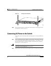
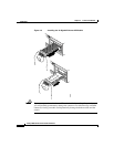
Connecting DC Power to the Switch
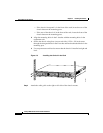
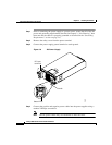
Step 5 Replace the safety cover over the power terminals.
Step 6 Connect the other end of the power cables to an DC-power input source. If both
power supplies will be used, make sure they are on different circuits.
Step 7 Turn on the power from the power source. The DC supply does not have an on/off
switch.
Step 8 Verify power supply operation by looking at the front panel power supply LEDs:
• The PS1 or PS2 LED is green when the power supply is functioning normally.
• The PS1 or PS2 LED is red when the power supply is not functioning
normally.
• The PS1 or PS2 LED is off when the power supply is not connected to a power
source.
From the system console, enter the show power command to display the power
supply and system status. For more information on this command, see the
command reference publication for your software release.
If the LEDs or show power command indicate a power or other system problem,
see
Chapter 5, “Troubleshooting the Installation,” for troubleshooting
information.