


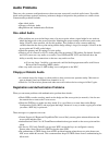
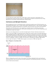
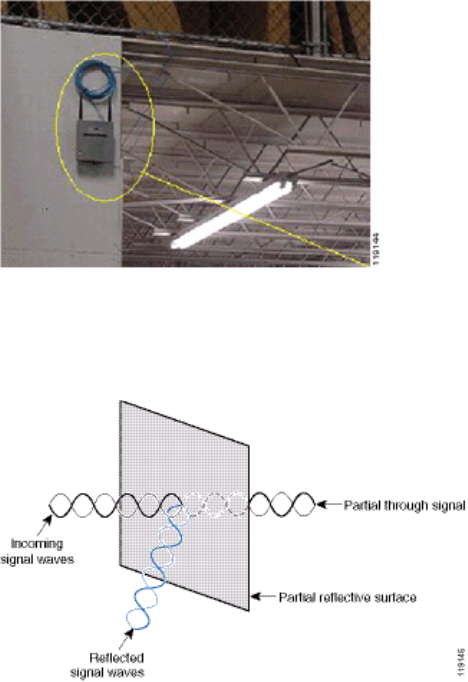
Figure 20 shows the signal propagation caused by the wall on which the access point is mounted.
Figure 20Signal Reflection Caused by a Wall
The preceding examples also apply when you place access points and antennas in or near the ceiling in a
standard Enterprise environment. If there are metal air ducts, elevator shafts, or other physical barriers that
can cause signal reflection or multipath interference, Cisco highly recommends that you move the antennas
away from those barriers. In the case of the elevator, move the antenna a few feet away in order to help
eliminate the signal reflection and distortion. The same is true with air ducts in the ceiling.
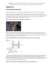
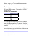
A survey conducted without sending and receiving packets is not sufficient. The I−beam example shows the
creation of null points that can result from packets that have CRC errors. Voice packets with CRC errors are
missed packets that adversely affect voice quality. In this example, those packets could be above the noise
floor measured by a survey tool. Therefore, it is very important that the site survey not only measures signal
levels but also generates packets and then reports packet errors.
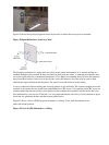
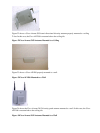
Figure 21 shows a Cisco AP1200 properly mounted to a ceiling T−bar, with the antennas in an
omni−directional position.
Figure 21Cisco AP1200 Mounted to a Ceiling