


2-6
Cisco 7401ASR Installation and Configuration Guide
OL-5419-01 B0
Chapter 2 Rack-Mounting, Tabletop Installation, and Cabling
Installing the Router
• A port adapter filler panel is installed if a port adapter or service adapter is not in place.
• The router will receive adequate ventilation (it is not being installed in an enclosed cabinet where
ventilation is inadequate).
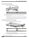
• If you plan to install the cable-management bracket, unpack and have handy the cable-management
bracket and one M4 x 20-mm screw.
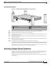
• An adequate chassis ground (earth) connection exists for your router chassis.
Note We strongly recommend that you provide a chassis ground connection. See the “Attaching a
Chassis Ground Connection” section on page 2-11 for instructions.
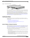
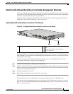
Following are the steps for installing a Cisco 7401ASR router on a workbench or tabletop:
Step 1 Remove any debris and dust from the tabletop or workbench, as well as the surrounding area. Also make
sure your path between the router and its new location is unobstructed.
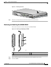
Step 2 On the chassis, ensure that the port adapter latch is in the locked position.
Step 3 Lift the chassis by placing your hands around the chassis sides and lifting the chassis from underneath.
To prevent injury, avoid sudden twists or moves.
Step 4 Place the router on the tabletop or workbench.
Step 5 Ensure that there is at least 3 inches (7.62 cm) of clearance at the inlet and exhaust vents of the router
and no exhaust air from other equipment will be drawn into the chassis. Also, ensure that there is
approximately 19 inches (48.3 cm) of clearance at the front and rear of the chassis.
This completes the general tabletop or workbench installation.
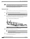
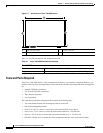
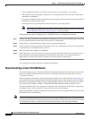
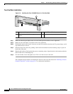
Rack-Mounting a Cisco 7401ASR Router
The chassis mounts to two rack posts with brackets that attach to either the front or the rear sides of the
chassis. The inside width between the two posts or mounting strips (left and right) must be at least
17.3 inches (43.9 cm).
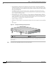
Some equipment racks provide a power strip along the length of one of the mounting strips. Figure 2-7
shows a typical four-post equipment rack with a power strip along one of the back posts. If your rack has
this feature, consider the position of the strip when planning fastener points to ensure that you will be
able to pull the port adapter, a GBIC, or CompactFlash Disk straight out of their respective slots.
The inlet and exhaust ports for cooling air are located on the front and rear of the chassis, respectively,
so multiple routers can be stacked in a rack with little or no vertical clearance.
Before beginning the installation, determine the type of rack you are using and whether or not you want
the chassis front- or rear-mounted.
Note If you are rear-mounting the chassis and want to use the cable-management bracket, you must purchase
a second rack-mount kit. You need another rack-mount bracket to attach to the front of the chassis. After
it is attached to the chassis, install the cable-management bracket to the rack-mount bracket.