


2-13
Cisco 7401ASR Installation and Configuration Guide
OL-5419-01 B0
Chapter 2 Rack-Mounting, Tabletop Installation, and Cabling
Connecting Port Adapter Cables
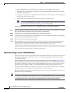
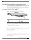
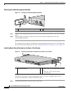
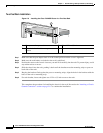
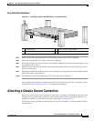
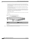
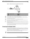
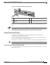
Figure 2-9 Attaching a Grounding Lug to the Chassis Grounding Connector
Step 2
Use the wire stripper to strip one end of the 6-AWG wire approximately 0.75 inches (19.05 mm).
Step 3 Insert the 6-AWG wire into the wire receptacle on the grounding lug.
Step 4 Use the crimping tool to carefully crimp the wire receptacle around the wire; this step is required to
ensure a proper mechanical connection.
Step 5 Insert the two screws through the holes in the grounding lug. (See Figure 2-9.)
Step 6 Use the Number 2 Phillips screwdriver to carefully tighten the screws until the grounding lug is held
firmly to the chassis. Do not overtighten the screws.
Step 7 Connect the opposite end of the grounding wire to the appropriate grounding point at your site to ensure
an adequate chassis ground.
This completes the procedure for attaching a chassis ground connection. Go to the following cabling
sections for information on attaching cables.
Connecting Port Adapter Cables
The instructions for connecting the cables for the port adapter installed in the Cisco 7401ASR router are
contained in the respective configuration note for each port adapter. For example, if you are connecting
the optical fiber cables for the PA-POS-OC3 port adapter, refer to the configuration note PA-POS-OC3
Packet OC3 Port Adapter Installation and Configuration at
http://www.cisco.com/univercd/cc/td/doc/product/core/7206/port_adp/sonet_pa/paposoc3/index.htm.
Port adapter documents are also available on the Documentation CD-ROM.
Note There are no cable connections to the VPN Acceleration Module (.
1 Chassis grounding connector 3 Screws
2 Grounding lug 4 Wire
50536
1
2
3
4