


Send documentation comments to mdsfeedback-doc@cisco.com.
1-19
Cisco MDS 9216 Switch Hardware Installation Guide
78-16165-01
Chapter 1 Product Overview
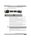
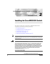
32 Port Fibre Channel Advanced Services Module
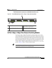
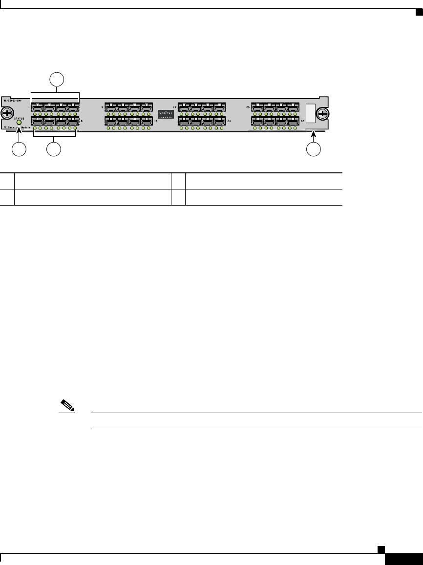
Figure 1-8 Fibre Channel Advanced Services Module
Each module draws power from the 42V supplied on the backplane with local
DC/DC power converters and regulators.
The control processor on the module provides power-on, offline, and online
diagnostics. The control processor can be used to configure devices on the
switching module and to gather statistical data from each port.
The control processor monitors the DC/DC power source and temperature. The
control processor signals the supervisor module and displays an alarm on its front
panel when a problem is detected.
The front panel on the services module provides basic status information, such as
power-on, self-test running, self-test passed, alarm, and ready.
The binary image for the services module is downloaded from the supervisor
module. Prior to the image download, the control processor on the switching
module runs from code stored on its local CompactFlash card.
Note Software downloads are only necessary when a revision of the code is needed.
The supervisor module can force a reset on the services module and controls
whether power is applied to the switching module.
If a single component or a set of components on the switching module fails, this
failure will not disable another switching module if that is the only failure in the
system.
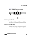
1 Status LED 3 Link and speed LEDs
2 1/2-Gbps Fibre Channel port group 4 Asset tag
94298
2
1 43
2
7
10
15
18
23
26
31