


Send documentation comments to mdsfeedback-doc@cisco.com.
Chapter 2 Installing the Cisco MDS 9216 Switch
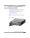
Removing and Installing Components
2-26
Cisco MDS 9216 Switch Hardware Installation Guide
78-16165-01
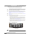
To install a module in slot 2 of the chassis, follow these steps:
Step 1 Verify that there is enough clearance to accommodate any interface equipment
that you connect directly to the nearby components.
Step 2 If a filler panel is installed, remove the two Phillips pan-head screws from the
filler panel and remove the panel. To remove a currently installed module, see the
“Removing and Installing Switching and Services Modules” section on
page 2-22.
Step 3 Open fully both ejector levers on the new or replacement module (see Figure 2-9
on page 2-23).
Step 4 Position the module in the chassis as follows:
a. Position the module in the slot, aligning the sides of the module carrier with
the slot guides on each side of the slot.
b. Slide the module carefully into the slot until the EMI gasket along the top
edge of the module makes contact with the supervisor module above it and
both ejector levers have closed to approximately 45 degrees with respect to
the module faceplate (see Figure 2-10 on page 2-24).
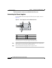
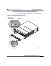
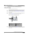
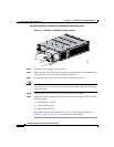
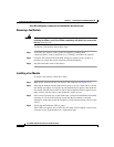
c. Grasp the two ejector levers using the thumb and forefinger of each hand and
press down to create a small 0.040 inch (1 mm) gap between the module's
EMI gasket and the module above it (see Figure 2-11).
Figure 2-11 Closing the Ejector Levers
Caution Do not press down too forcefully on the levers because they can bend.
FAN
STATUS
FAN-MOD-2
1
2
91677
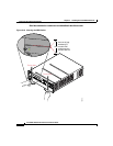
Ejector levers flush with
module faceplate
1 2 3 4 5 6 7 8 9 10 11 12 13 14 15 16
S
TA
TU
S
SY
S
TE
M
R
ES
ET
CONSOLE
MGMT 10/100
MDS 9216
COM1
1 2 3 4 5 6 7 8 9 10 11 12 13 14 15 16