


1-6
Cisco ASR 903 Router Hardware Installation Guide
OL-25178-05
Chapter 1 Cisco ASR 903 router Overview
Cisco ASR 903 router Features
AC Power Specifications
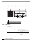
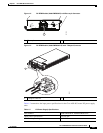
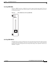
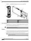
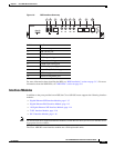
Fan Tray
The fan tray modules supported on the router are:
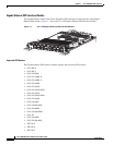
• A903-FAN, Figure 1-4
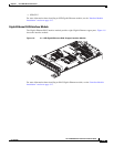
• A903-FAN-E, Figure 1-5
The fan tray has the following hardware features:
• It provides side-to-side forced air cooling
• It provides redundant fans
• It is field replaceable
• It contains status LEDs
• It contains an alarm port with four external alarm inputs
For more information about air flow guidelines, see Air Flow Guidelines, page 2-11. For instructions on
how to install the fan tray, see Installing the Fan Tray, page 3-10. For a summary of the LEDs on the fan
tray, see “LED Summary” section on page 5-8
Maximum input voltage -72 VDC
Output voltage +12 VDC
Wire gauge for DC input power connections 12 AWG minimum for -48/-60 VDC.
8 AWG minimum for 24 VDC.
Connector accepts 8 AWG maximum.
Power dissipation 600 W
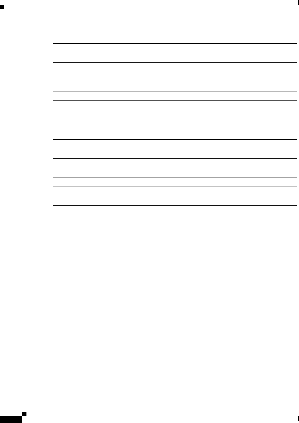
Table 1-3 AC Power Supply Specifications
Part number A900-PWR550-A
Input power specification 115VAC/ 230VAC
Input voltage 85/264 VAC
Minimum input voltage 85 VAC
Maximum input voltage 264 VAC
Minimum output voltage 12V
Maximum output voltage 12.4V
Power dissipation 600 W
Table 1-2 DC Power Supply Specifications